
Method and apparatus for packet wireless telecommunications

a packet wireless and wireless technology, applied in the field of packet wireless telecommunications, can solve the problems of low data rate traffic flow, large scheduling overhead, low channel utilization, etc., and achieve the effects of reducing transmission and reception latency, simple receiver structure, and large capacity

Active Publication Date: 2008-10-30
ALCATEL LUCENT SAS
View PDF6 Cites 81 Cited by
  • Summary
  • Abstract
  • Description
  • Claims
  • Application Information

AI Technical Summary

Benefits of technology

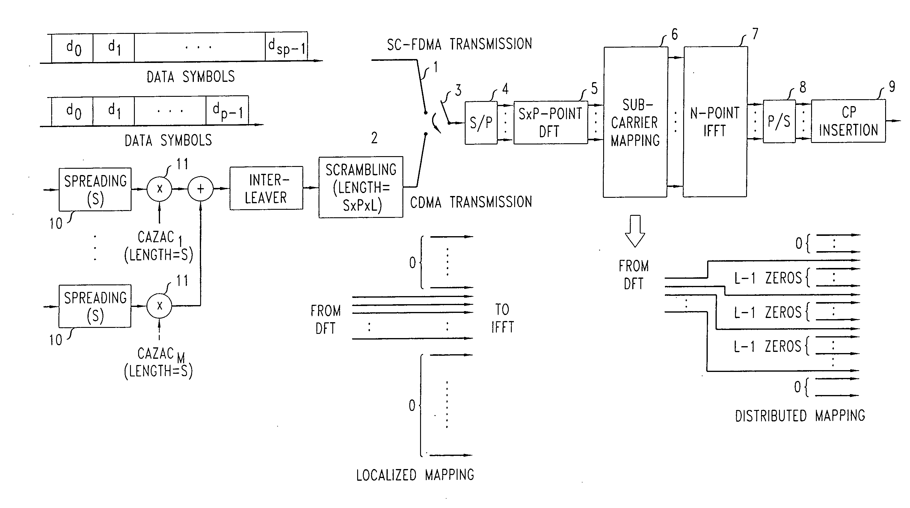
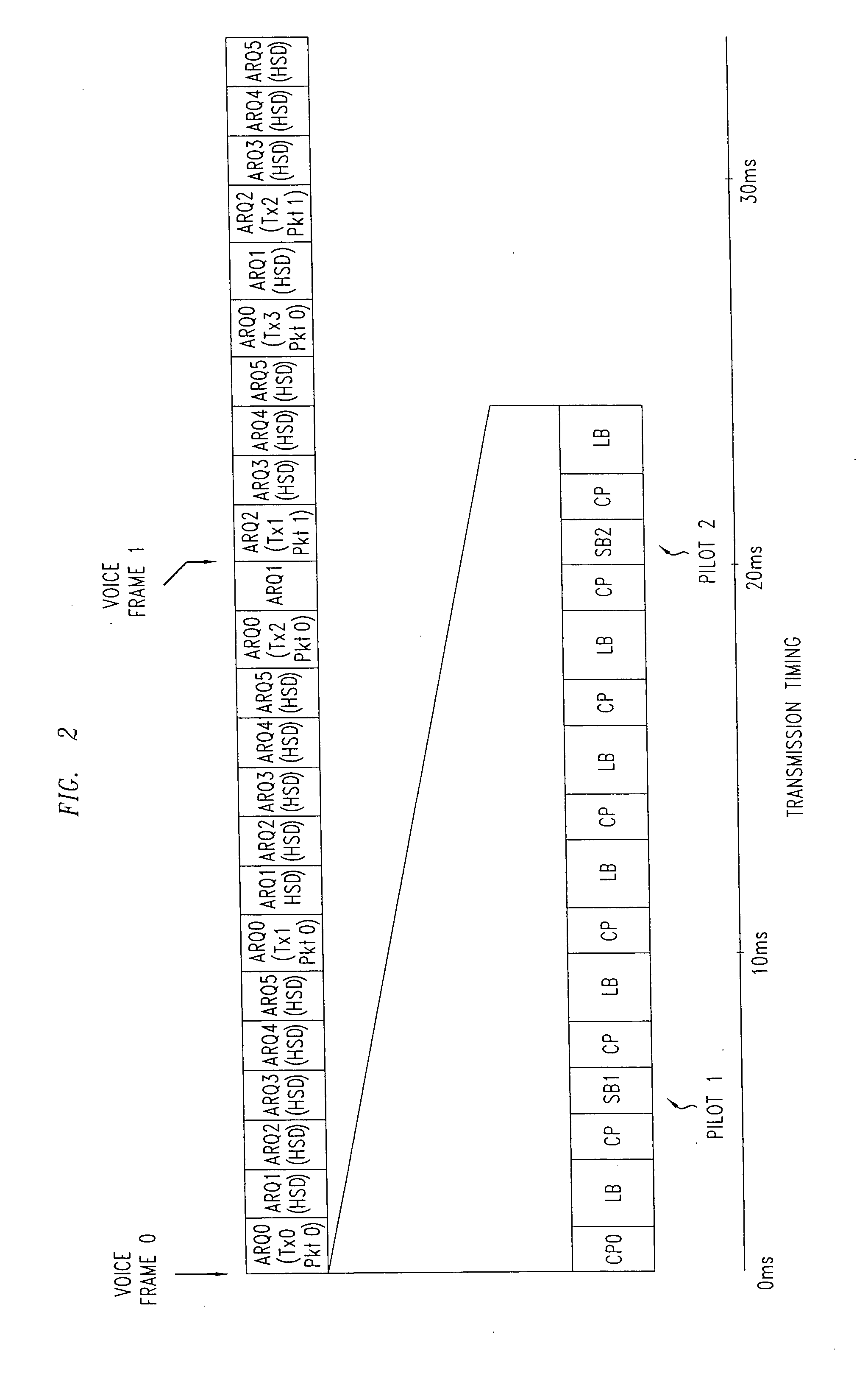
[0007]In one aspect of the invention, a method for transmitting data via a packet wireless telecommunications network includes the steps of: applying a Code Division Multiple Access (CDMA) scheme to data to encode it. The encoded data is transmitted in an Orthogonal Frequency Division Multiplexing (OFDM) frame structure which includes a cyclic prefix (CP). This allows autonomous transmission, and is particularly advantageous where the data payloads are small, for example for voice over IP (VoIP) traffic and control signals. It avoids the need to explicitly schedule time, frequency and code resources at each transmission instance. Thus, information bits may be transmitted without scheduling overhead. Reduced latency in transmission and reception is possible. Any OFDM frame structure with CP is applicable to the invention, including generic frame structure and TDD alternative frame structure. In one embodiment, the invention may be implemented with a simple receiver structure to provide potentially large capacity. Thus, a large number of users for the same radio resource may be supported, giving base station cost savings.
[0008]The data may be encoded by using a CDMA scheme by block repetition followed by scrambling by a Constant-Amplitude Zero Auto-Correlation (CAZAC) sequence. Users with similar radio propagation conditions may be placed in a group and assigned different orthogonal CAZAC sequences. Different groups are assigned different basic CAZAC sequences. This facilitates receiver design using a successive interference cancellation (SIC) receiver. In another aspect, users are assigned different pseudo-random sequences with low correlation properties.
[0015]Various frequency reuse schemes are considered in LTE [TR25.814, R1-061375]. The current working assumption on frequency reuse is (a) semi-static frequency allocation on the order of days and (b) dynamic frequency allocation on the order of seconds. Dynamic frequency allocation can be made to adapt to cell loading or user loading variations. In this case, the reuse pattern can change between (1,1) reuse and (1,3). In (1,3) reuse, only ⅓ of the sub-carriers is available to a user. With the flexibility of SC-FDMA structure, soft frequency reuse for cell-edge users is envisioned to mitigate the impact of co-channel interference. The proposed CDMA transmission can softly adapt to bandwidth changes by changing the SF. If the full bandwidth is available, VoIP transmission with SF=12 can be supported. When ⅓ of the spectrum is available, spreading factor can be reduced to SF=4 to preserve the rates of each user. In this case, fewer numbers of users can be multiplexed in a given CDMA time-frequency resource. For some applications, capacity in terms of number of users may be more important than preserving per-user data rates. In such a scenario, per-user data rate may be reduced while preserving the user capacity, by reducing the modulation order, or by limiting the number of HARQ processes per user.

Problems solved by technology

This may add large amount of scheduling overhead both in the uplink and the downlink control channels, and may be inefficient to support large number of delay-sensitive, low data rate traffic flows.
This may result in low channel utilization.

Method used


Image

  • Method and apparatus for packet wireless telecommunications
  • Method and apparatus for packet wireless telecommunications
  • Method and apparatus for packet wireless telecommunications

Examples


Embodiment Construction

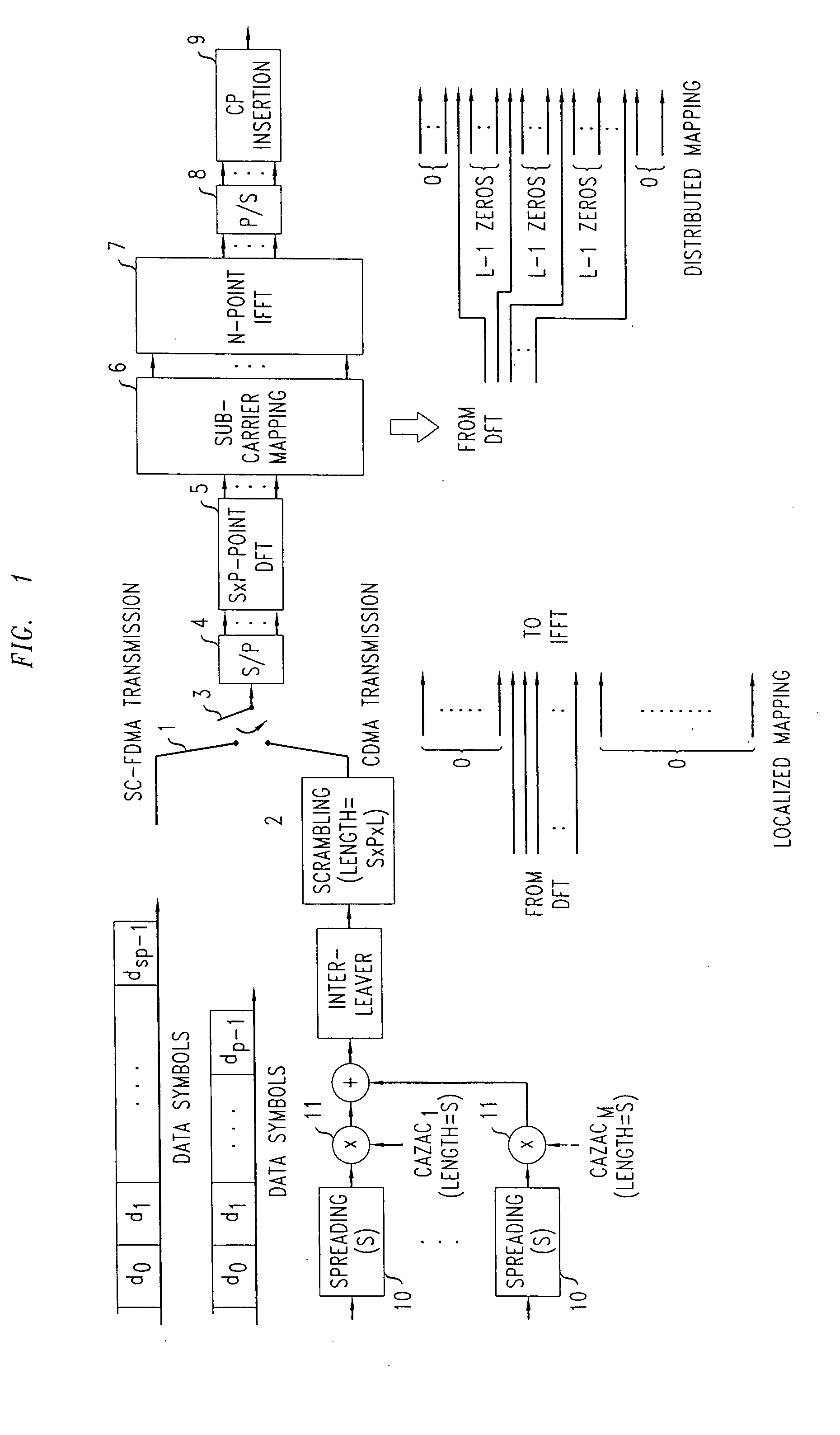
[0025]With reference to FIG. 1, a user equipment (UE) includes a transmitter for time multiplexing CDMA and SC-FDMA transmissions and transmitting them in the uplink of an LTE-compliant network. It includes first and second branches 1 and 2 to give different paths through the transmitter for high rate data traffic and voice traffic respectively. In the first branch 1, concerned with SC-FDMA transmission, a stream of data symbols d0, d1 to dsp−1 is applied via a selector 3 to a serial to parallel data converter 4, the outputs of which are then applied to a DFT 5. This is followed by sub-carrier mapping at 6, an N-point inverse fast Fourier transform (IFFT) 7 and a parallel to serial data converter 8. The cyclic prefix CP is inserted at 9 prior to transmission on the uplink to a base station. This is the mode used for data having less stringent latency requirements and fast data rates.

[0026]The transmitter also includes the second branch 2 for operation in the CDMA mode for voice traf...


PUM


Abstract

In a wireless telecommunications network, a Code Division Multiple Access (CDMA) scheme is applied to data to encode it. The encoded data transmitted in the uplink using an Orthogonal Frequency Division Multiplexing (OFDM) frame structure including a cyclic prefix (CP). The CDMA encoded data may be time multiplexed with Single Carrier-Frequency Division Multiple Access (SC-FDMA) transmissions. The CDMA transmissions may be used for relatively small payloads, such as those associated with voice traffic and control signals, and the SC-FDMA transmissions used for higher date rate transmissions. This enables autonomous transmission, without scheduling, for smaller payloads. A transmitter includes a selector 3 for performing time multiplexing in the uplink, the required mode being indicated by the Hybrid Automatic Repeat Request (HARQ) ID. A first branch 1 carries SC-FDMA data and a second branch 2 carries data to be transmitted as a CDMA scheme. A CAZAC code may be used in encoding the CDMA data.

Description

FIELD OF THE INVENTION[0001]The present invention relates to a method and apparatus for packet wireless telecommunications, and more particularly, but not exclusively, to those that are compliant with UMTS Long Term Evolution (LTE) standards.BACKGROUND OF THE INVENTION[0002]Universal Mobile Telecommunications System (UMTS) is a current standard for wireless radio telecommunication networks. Efforts are being directed to develop an evolved standard, UMTS Long Term Evolution (LTE), also known as E-UTRA (Evolved UMTS Terrestrial Radio Access).[0003]In E-UTRA, in the downlink, orthogonal frequency division multiplexing (OFDM) is proposed. In OFDM, the sub-carriers are orthogonal to one another and each is modulated with a data stream. The downlink data modulation may be performed using QPSK, 16QAM or 64QAM.[0004]In the uplink, single carrier frequency division multiple access (SC-FDMA) has been introduced, in which discrete Fourier transform (DFT) precoding is applied to spread OFDM sig...

Claims


Application Information

Patent Timeline
IPC IPC(8): H04B7/216
CPCH04L1/0006H04L1/1812H04L27/2602H04L27/2626H04L27/2647H04L27/26H04L1/18
Inventor LEE, JUNG AHTATESH, SAIDZHOU, HAI
Owner ALCATEL LUCENT SAS
Learn More