
Method of operating a plug-in hybrid electric vehicle

a hybrid electric vehicle and plug-in technology, applied in the field of plug-in hybrid electric vehicle operation, can solve the problems of purely electric vehicles lacking an on-board means to recharge, and the cost of recharging is proportional to the cost of consumable fuel, and achieve the effect of disabling the operation of plug-in hybrid electric vehicl

Inactive Publication Date: 2008-11-06
GM GLOBAL TECH OPERATIONS LLC
View PDF4 Cites 101 Cited by
  • Summary
  • Abstract
  • Description
  • Claims
  • Application Information

AI Technical Summary

Benefits of technology

[0009]The above features and advantages and other features and advantages of the present invention are readily apparent from the following detailed description of the best modes for carrying out the invention when taken in connection with the accompanying drawings.
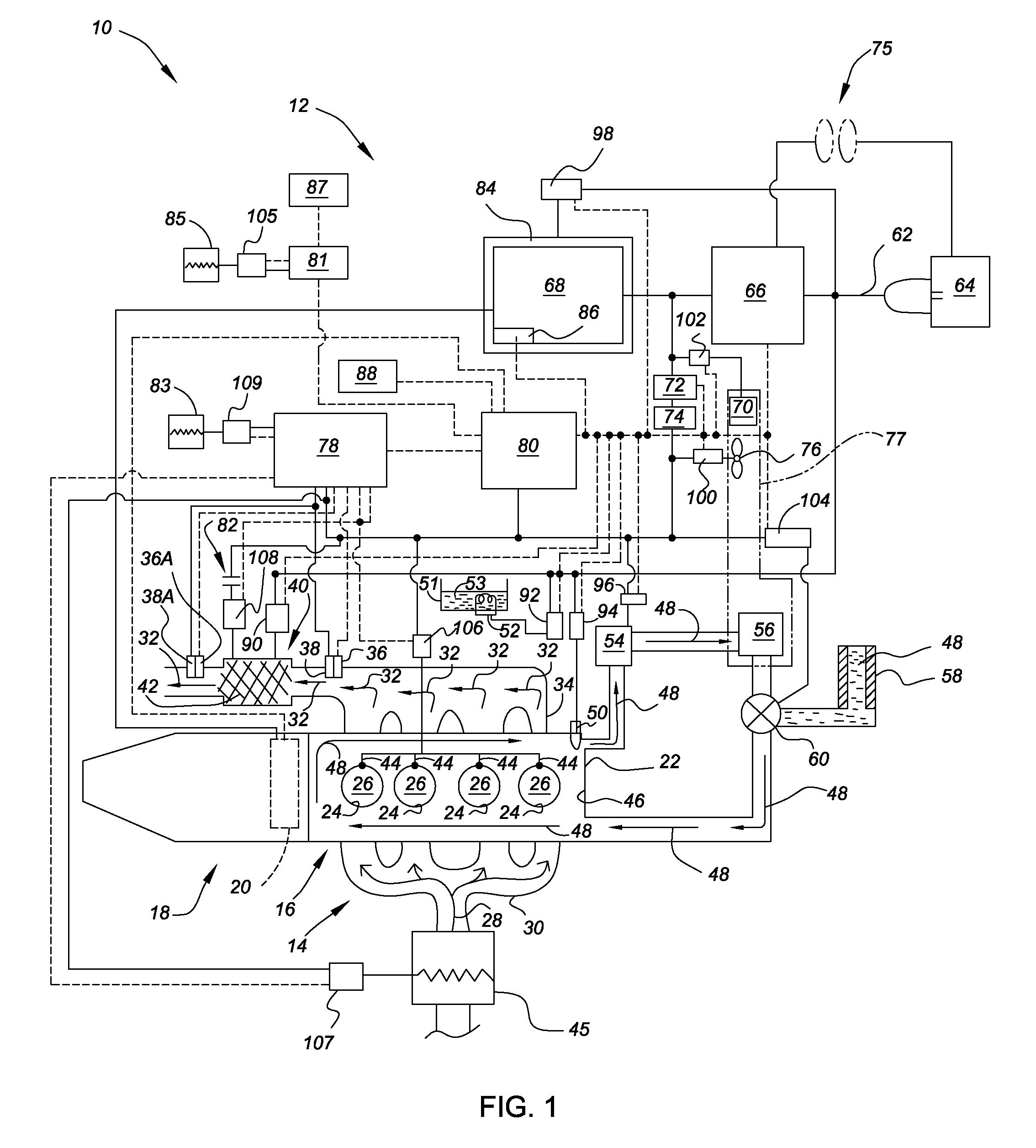
[0010]FIG. 1 is a schematic diagrammatic illustration of a portion of a plug-in hybrid electric vehicle incorporating a control system for a hybrid powertrain consistent with the present invention; and
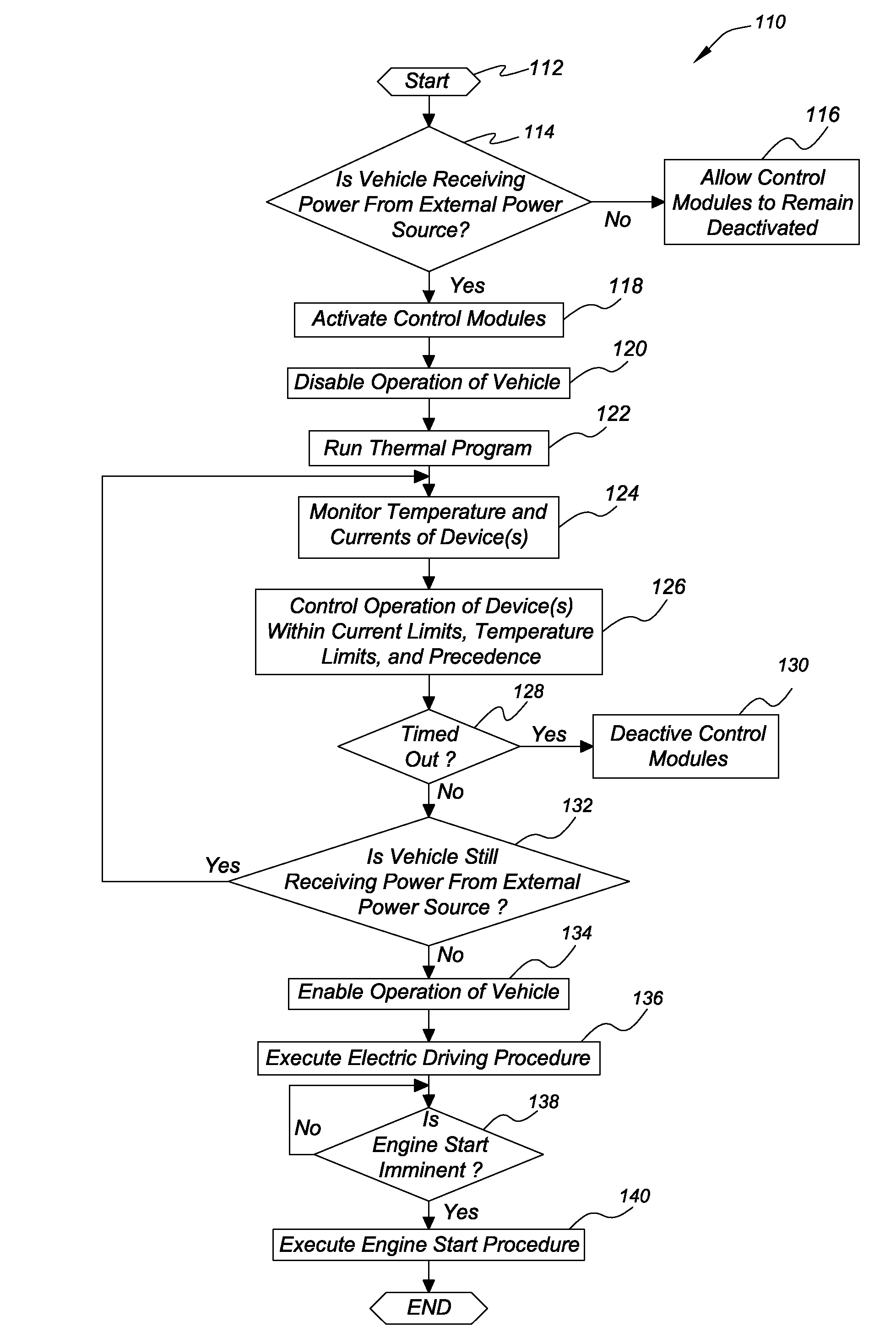
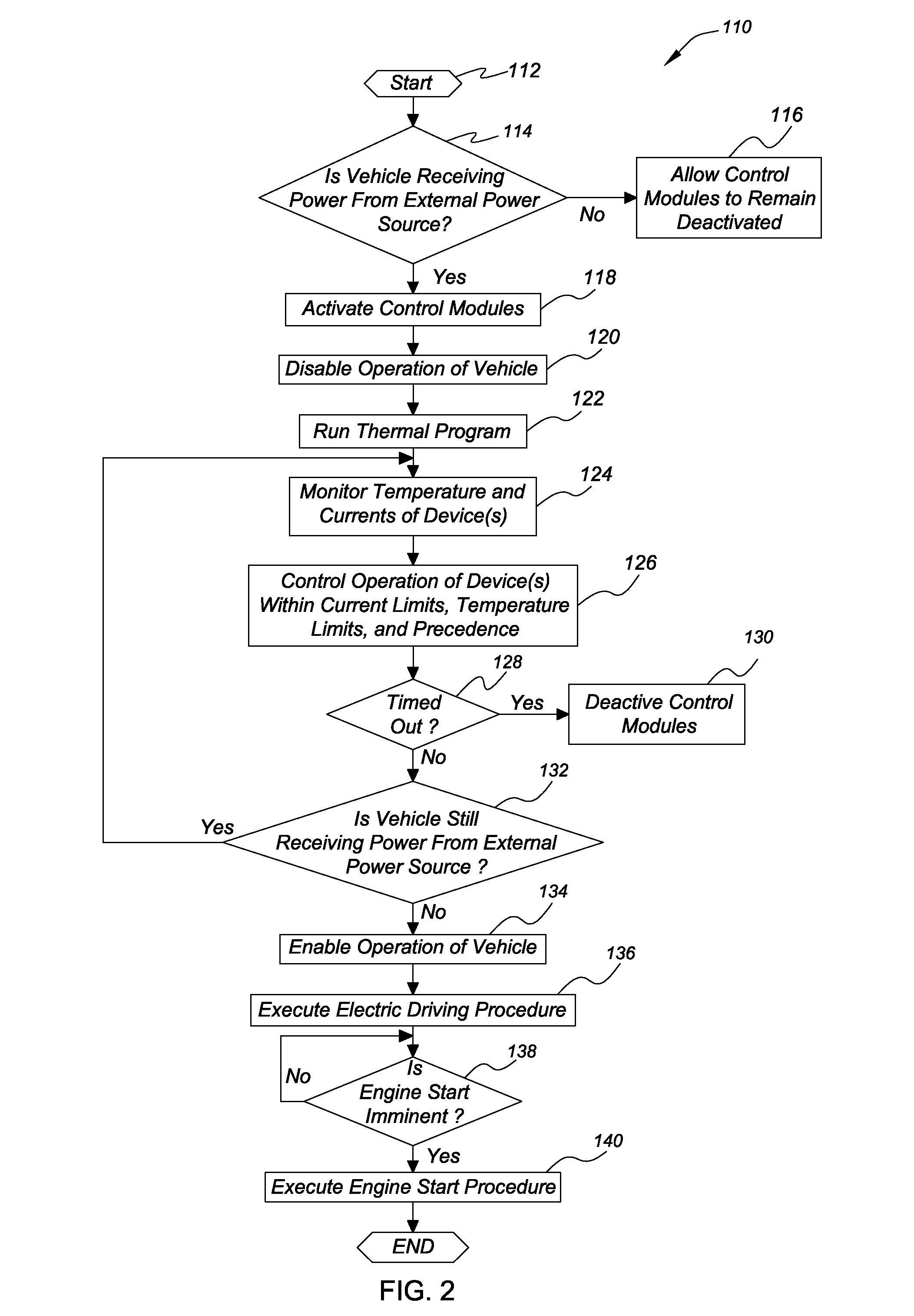
[0011]FIG. 2 is a method, depicted in flow chart format, illustrating various steps for operating the plug-in hybrid electric vehicle of FIG. 1.
[0012]Referring to FIG. 1, there is shown a portion of a plug-in hybrid electric vehicle, generally indicated at 10. The plug-in hybrid electric vehicle 10 includes a control system 12 and a hybrid powertrain 14. The hybrid powertrain 14 includes an internal combustion engine 16, such as a spark-ignited or a compression-ignited engine, having a transmission 18 operatively connected thereto. The internal combustion engine 16 of FIG. 1 is a compression ignited diesel engine; however, those skilled in the art will recognize the claimed invention may be applied to hybrid powertrains incorporating a spark-ignited engine while remaining within the scope of that which is claimed. The internal combustion engine 16 provides torque to the transmission 18, which in turn, provides the requisite driving force to effect movement of the plug-in hybrid electric vehicle 10. At least one motor 20 may be provided to effect movement of the plug-in hybrid electric vehicle 10 in conjunction with, or in lieu of that supplied by the internal combustion engine 10, thereby providing hybrid functionality to the hybrid powertrain 14.
[0013]The internal combustion engine 16 includes a cylinder block 22 defining a plurality of cylinders 24. Each of the cylinders 24 at least partially defines a variable volume combustion chamber 26. Intake air, indicated by arrow 28, is communicated to each of the combustion chambers 26 of the internal combustion engine 16 through an intake manifold 30. A mixture of intake air 28 and fuel, not shown, is subsequently combusted within the combustion chambers 26 and the products of combustion, indicated by arrow 32, are exhausted from the internal combustion engine through an exhaust manifold 34. Lambda sensors or oxygen sensors 36 and 36A are mounted with respect to the exhaust manifold 34 and operate to determine the percentage of oxygen contained within the products of combustion 32 to determine the air to fuel ratio of the internal combustion engine 16 during operation. The air to fuel ratio is especially important to enable optimal performance and efficiency of the internal combustion engine 16. Heaters 38 and 38A are mounted with respect to the respective oxygen sensors 36 and 36A and are operable to heat the oxygen sensors 36 and 36A to enable operation during cold starting or re-start conditions of the internal combustion engine 16.
[0014]A catalyst 40, such as a three-way catalyst, is mounted downstream of the exhaust manifold 34 and is operable to reduce certain regulated emission constituents, such as oxides of nitrogen and hydrocarbons, from within the products of combustion 32. The catalyst 40 includes a catalyst heater 42. The catalyst heater 42 is preferably capable of heating or warming the catalyst 40 to, or close to, the catalyst light-off temperature during cold start of the internal combustion engine 16, thereby reducing the regulated emission constituents at start up of the internal combustion engine 16. To aid in starting the internal combustion engine 16, a glow plug 44 is provided within each of the combustion chambers 26. The glow plugs 44 operate to heat intake air 28 and fuel within the combustion chambers 26, thereby providing a more favorable condition for combustion within the combustion chambers 26. Additionally, an intake air heater 45 is provided at the inlet of the intake manifold 30 to heat the intake air 28 prior to entering the combustion chambers 26, thereby providing a more favorable condition for combustion within the combustion chambers 26 and to reduce the likelihood of white smoke production during cold start of the internal combustion engine 16.
[0015]The cylinder block 22 further defines a water jacket 46 configured to contain a predetermined amount of engine coolant, indicated by arrows 48. The engine coolant 48 extracts heat energy generated by operation of the internal combustion engine 16. A engine coolant heater 50 is provided to warm the coolant prior to the starting of the internal combustion engine 16 to reduce the friction and hydrocarbon emissions and improve combustion stability at start-up. Similarly, a engine oil heater 52 is mounted with respect to an oil reservoir or pan 51, shown apart from the internal combustion engine 16 for purposes of clarity, and operates to heat engine oil 53 contained therein. By heating the engine oil 53 prior to starting the internal combustion engine 16, the viscosity of the engine oil 53 is reduced such that the operating efficiency of the internal combustion engine is increased. A coolant circulation pump 54 is provided to circulate engine coolant 48 through the internal combustion engine 16 and a heater core 56 to provide heat to the interior of the plug-in hybrid electric vehicle 10 when the internal combustion engine 16 is not operating. An insulated storage tank 58, such as a dewar tank, is provided to contain a predetermined amount of heated engine coolant 48. A valve 60 is provided to selectively discharge the heated coolant 48 from the insulated storage tank 58 to warm the internal combustion engine 16. Those skilled in the art of vehicle design will recognize that a similar dewar tank and valve configuration may be used to store and discharge heated oil 53 to the internal combustion engine 16 such as, for example, a dry sump lubrication system.

Problems solved by technology

The purely electric vehicle typically lacks an on-board means to recharge the battery and therefore must be recharged from an external power source, such as household alternating current, a publicly accessible recharging facility, or any other external power source compatible with the recharging system of the vehicle.
With typical hybrid electric vehicles, the recharging of the battery using power from the internal combustion engine makes the cost of recharging proportional to the cost of consumable fuel.

Method used


Image

  • Method of operating a plug-in hybrid electric vehicle
  • Method of operating a plug-in hybrid electric vehicle
  • Method of operating a plug-in hybrid electric vehicle

Examples


Embodiment Construction

[0012]Referring to FIG. 1, there is shown a portion of a plug-in hybrid electric vehicle, generally indicated at 10. The plug-in hybrid electric vehicle 10 includes a control system 12 and a hybrid powertrain 14. The hybrid powertrain 14 includes an internal combustion engine 16, such as a spark-ignited or a compression-ignited engine, having a transmission 18 operatively connected thereto. The internal combustion engine 16 of FIG. 1 is a compression ignited diesel engine; however, those skilled in the art will recognize the claimed invention may be applied to hybrid powertrains incorporating a spark-ignited engine while remaining within the scope of that which is claimed. The internal combustion engine 16 provides torque to the transmission 18, which in turn, provides the requisite driving force to effect movement of the plug-in hybrid electric vehicle 10. At least one motor 20 may be provided to effect movement of the plug-in hybrid electric vehicle 10 in conjunction with, or in l...


PUM


Abstract

A method of operating a plug-in hybrid electric vehicle is provided including the steps of: A) determining whether the plug-in hybrid electric vehicle is receiving power from an external power source; B) disabling the operation of the plug-in hybrid electric vehicle and executing a thermal program if the plug-in hybrid electric vehicle is receiving power from the external power source, wherein the thermal program includes charging a high voltage battery and monitoring the state of charge of the high voltage battery; C) determining if the plug-in hybrid electric vehicle continues to receive power from the external power source; and D) enabling operation of the plug-in hybrid electric vehicle if the plug-in hybrid electric vehicle is no longer receiving power from the external power source.

Description

TECHNICAL FIELD[0001]The present invention relates to a method of operating a plug-in hybrid electric vehicle.BACKGROUND OF THE INVENTION[0002]Hybrid electric vehicles, which are powered with a combination of consumable fuel, such as fossil fuels, and electricity, typically stored within a battery, are becoming more prevalent in the automotive market. Such hybrid electric vehicles are displacing purely electric vehicles, as well as conventional vehicles powered solely by internal combustion engines.[0003]The purely electric vehicle typically lacks an on-board means to recharge the battery and therefore must be recharged from an external power source, such as household alternating current, a publicly accessible recharging facility, or any other external power source compatible with the recharging system of the vehicle. By contrast, the hybrid electric vehicle is typically not recharged from an external power source, but is instead recharged using energy from an onboard means.[0004]Ty...

Claims


Application Information

Patent Timeline
Patent Type & Authority Applications(United States)
IPC IPC(8): G06F17/00G01M17/00
CPCB60K6/24Y02T10/70B60K2001/005B60K2001/008B60L3/0046B60L11/005B60L11/14B60L11/1874B60L11/1875B60L2240/441B60L2240/443B60L2240/445B60W10/06B60W10/08B60W10/26B60W20/00B60W2510/0638B60W2510/0657B60W2510/0676B60W2510/244Y02T10/54Y02T10/6226Y02T10/6269Y02T10/6278Y02T10/6286Y02T10/6295Y02T10/7005Y02T10/7022Y02T10/705Y02T10/7077Y02T90/14B60K6/28B60Y2400/112B60K6/485B60K2006/268B60L50/16B60L50/40B60L58/12B60L58/26B60L58/27Y02T10/40Y02T10/62Y02T10/7072B60W20/50
Inventor RASK, ERIC M.BURNS, ROBERT D.THEOBALD, MARK A.
Owner GM GLOBAL TECH OPERATIONS LLC
Learn More