Apparatus and method for hybrid machining a workpiece

a technology of hybrid machining and workpiece, which is applied in the direction of electrical-based machining electrodes, vibration holders of electrical devices, manufacturing tools, etc., can solve the problems of high machine and machining costs, difficult-to-machine materials, and stringent design requirements (high precision, complex shapes, and high surface quality). achieve the effect of high-speed electro-erosion process

Active Publication Date: 2008-11-13
GENERAL ELECTRIC CO
View PDF25 Cites 20 Cited by
  • Summary
  • Abstract
  • Description
  • Claims
  • Application Information

AI Technical Summary

Problems solved by technology

Today's manufacturing industry is facing challenges from advanced difficult-to-machine materials (tough super alloys, ceramics, and composites), stringent design requirements (high precision, complex shapes, and high surface quality), machine, and machining costs.
The greatly-improved thermal, chemical, and mechanical properties of the material (such as improved strength, heat resistance, wear resistance, and corrosion resistance), while having yielded enormous economic benefits to manufacturing industries through improved product performance and product design, are making traditional machining processes unable to machine them or unable to machine them economically.
In addition to the advanced materials, stringent design requirements also pose major problems in manufacturing industry.
Traditional machining is often ineffective in machining these parts.
One critical limitation, however, is that EDM only works with materials that are electrically conductive.
It is limited, however, to electrically conductive materials.
However, some advanced difficult-to-machine materials, such as titanium and titanium alloys, and stringent design requirements still pose major problems in the manufacturing industry.
Titanium remains difficult to machine by HSEE due to lower thermal conductivity and inconsistent molten chip ejection during cutting as compared to machining other alloys, such as nickel-based alloys and the like.

Method used


Image

  • Apparatus and method for hybrid machining a workpiece
  • Apparatus and method for hybrid machining a workpiece
  • Apparatus and method for hybrid machining a workpiece

Examples


Embodiment Construction

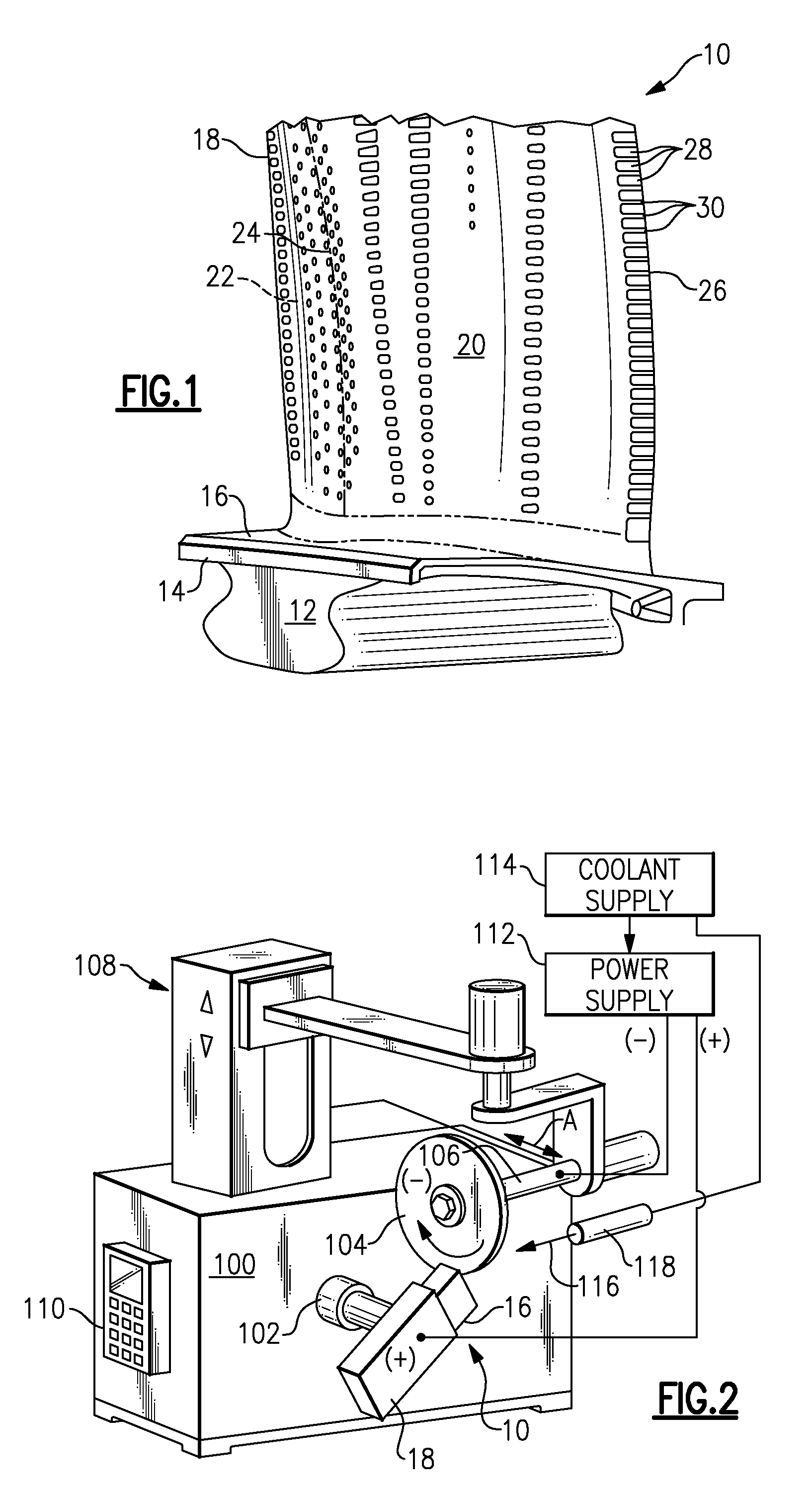
[0037]Referring to the drawings wherein identical reference numerals denote the same elements throughout the various views, FIG. 1 illustrates an exemplary turbine blade 10. The turbine blade 10 includes a dovetail 12, which may have any suitable form including tangs that engage complementary tangs of a dovetail slot in a rotor disk (not shown) for radially retaining the blade 10 to the disk as it rotates during operation. A blade shank 14 extends radially upwardly from the dovetail 12 and terminates in a platform 16 that projects laterally outwardly from and surrounds the shank 14. A hollow or solid airfoil 18 extends radially outwardly from the platform 16 and into the hot gas stream. The airfoil 18 has a concave pressure side wall 20 and a convex suction side wall 22 joined together at a leading edge 24 and at a trailing edge 26. The airfoil 18 may take any configuration suitable for extracting energy from the hot gas stream and causing rotation of the rotor disk. The blade 10 is...


PUM

PropertyMeasurementUnit
DC voltageaaaaaaaaaa
DC voltagesaaaaaaaaaa

Abstract

An apparatus and method for hybrid machining a workpiece is disclosed. The apparatus includes a mandrel for supporting the workpiece adjacent a cutter mounted on an arbor. A workpiece is powered as an anode and the cutter is powered as a cathode, and a cutting fluid or coolant is circulated therebetween. The cutter is made of a conductive material and a non-conductive abrasive material to maximize the amount of material removed from the workpiece. The coolant includes one or more additives to enhance the electrical discharge between the cutter and the workpiece. The cutter is moved relative to the workpiece to remove material from the workpiece at a predetermined depth of cut using an enhanced high-speed electro-erosion (HSEE) process in which both HSEE and abrasive machining processes are used. The workpiece may then be finish machined to a final shape of the titanium article, such as a dovetail of a turbine blade.

Description

BACKGROUND[0001]The invention relates generally to machining of an advanced material, and in particular to hybrid machining a titanium article, such as an airfoil of a gas turbine engine.[0002]Today's manufacturing industry is facing challenges from advanced difficult-to-machine materials (tough super alloys, ceramics, and composites), stringent design requirements (high precision, complex shapes, and high surface quality), machine, and machining costs.[0003]Advanced materials play an increasingly important role in modern manufacturing industries, especially, in aircraft, automobile, tool, die and mold making industries. The greatly-improved thermal, chemical, and mechanical properties of the material (such as improved strength, heat resistance, wear resistance, and corrosion resistance), while having yielded enormous economic benefits to manufacturing industries through improved product performance and product design, are making traditional machining processes unable to machine the...

Claims


Application Information

Patent Timeline
Patent Type & Authority Applications(United States)
IPC IPC(8): B23H9/10
CPCB23H1/04B23H1/06B23H1/08B23H5/04B23H9/10B23H5/08
Inventor TRIMMER, ANDREW LEEWEI, BINLAMPHERE, MICHAEL SCOTT
Owner GENERAL ELECTRIC CO
Why Eureka
Try Eureka