Virtual Electrode Mineral Particle Disintegrator

a technology of mineral particle disintegrator and electrode, which is applied in the direction of dislodging machine, earth drilling and mining, grain treatment, etc., can solve the problems of low conductivity, rock fragmentation, and fracture of rock

Active Publication Date: 2008-11-13
SDG LLC
View PDF39 Cites 26 Cited by
  • Summary
  • Abstract
  • Description
  • Claims
  • Application Information

AI Technical Summary

Benefits of technology

[0049]FIG. 32 is a graph showing dielectric strength versus delay to bre...

Problems solved by technology

The expansion of the hot gases created by the arc fractures the rock.
This expansion pressure fails the rock in tension, thus creating rock fragments.
However, insulating drilling fluid must provide high dielectric strength to provide high electric fields at the electrodes, low conductivity to provide low leakage current during the delay time from application of the voltage until the arc ignites in the rock, and high relative permittivity to shift a higher proportion of the electric field into the rock near the electrodes.
Water provides high relative permittivity, but has high conductivity, creating high electric charge losses.
In the deionized condition, water is very corrosive and will dissolve many materials, including metals.
Even when deionized, water still has such sufficient conductivity ...

Method used


Image

  • Virtual Electrode Mineral Particle Disintegrator
  • Virtual Electrode Mineral Particle Disintegrator
  • Virtual Electrode Mineral Particle Disintegrator

Examples


example 1

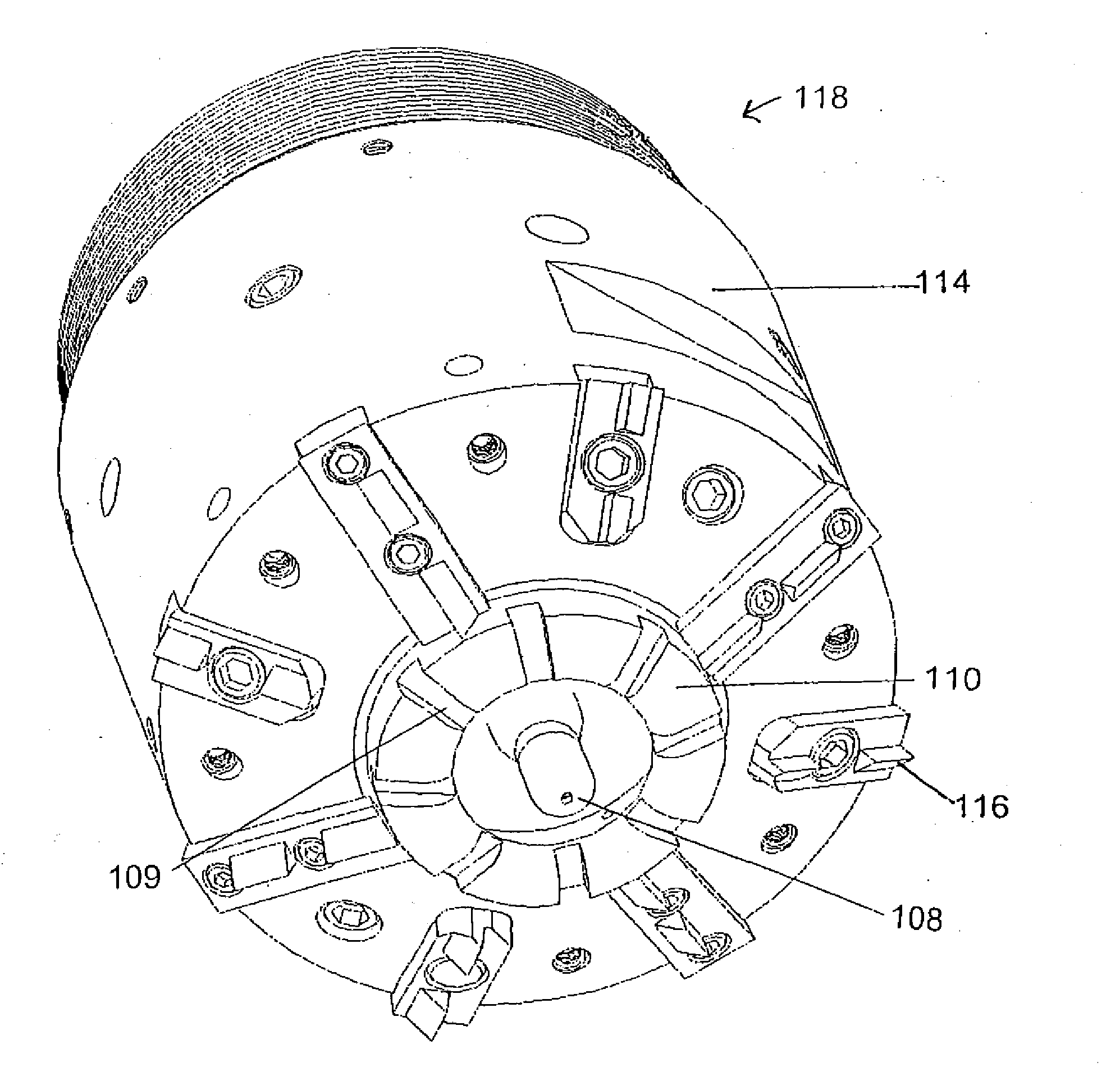
[0157]An apparatus utilizing FAST Drill technology in accordance with the present invention was constructed and tested. FIG. 31 shows FAST Drill bit 114, the drill stem 216, the hydraulic motor 218 used to turn drill stem 216 to provide power to mechanical teeth disposed on drill bit 114, slip ring assembly 220 used to transmit the high voltage pulses to the FAST bit 114 via a power cable inside drill stem 216, and tank 222 used to contain the rocks being drilled. A pulsed power system, contained in a tank (not shown), generated the high voltage pulses that were fed into the slip ring assembly. Tests were performed by conducting 150 kV pulses through drill stem 216 to the FAST Bit 114, and a pulsed power system was used for generating the 150 kV pulses. A drilling fluid circulation system was incorporated to flush out the cuttings. The drill bit shown in FIG. 5 was used to drill a 7 inch diameter hole approximately 12 inches deep in rock located in a rock tank. A fluid circulation s...

example ii

[0158]A high permittivity fluid comprising a mixture of castor oil and approximately 20% by volume butylene carbonate was made and tested in accordance with the present invention as follows:

1. Dielectric Strength Measurements.

[0159]Because this insulating formulation of the present invention is intended for high voltage applications, the properties of the formulation were measured in a high voltage environment. The dielectric strength measurements were made with a high voltage Marx bank pulse generator, up to 130 kV. The rise time of the Marx bank was less than 100 nsec. The breakdown measurements were conducted with 1-inch balls immersed in the insulating formulation at spacings ranging from 0.06 to 0.5 cm to enable easy calculation of the breakdown fields. The delay from the initiation of the pulse to breakdown was measured. FIG. 32 shows the electric field at breakdown plotted as a function of the delay time in microseconds. Also included are data from the Charlie Martin models f...


PUM


Abstract

The present invention provides for a method and apparatus for breaking mineral particles comprising suspending the particles in a liquid flowing in a conduction path, the liquid comprising a dielectric constant higher than the particles and wherein an electric voltage pulse is sent to electrodes to pass an electric field in the mineral particles with sufficient stress to fracture the mineral particles.

Description

CROSS-REFERENCE TO RELATED APPLICATIONS[0001]This application is a continuation-in-part of U.S. patent application Ser. No. 11 / 208,950, entitled “Virtual Electrode Mineral Particle Disintegrator,” filed on Aug. 19, 2005 which itself claims the benefit of the filing of U.S. Provisional Patent Application Ser. No. 60 / 603,509, entitled “Electrocrushing FAST Drill and Technology, High Relative Permittivity Oil, High Efficiency Boulder Breaker, New Electrocrushing Process, and Electrocrushing Mining Machine,” filed on Aug. 20, 2004, and the specifications and claims of those applications are incorporated herein by reference.BACKGROUND OF THE INVENTION[0002]1. Field of the Invention (Technical Field)[0003]The present invention relates to pulse powered drilling apparatuses and methods. The present invention also relates to insulating fluids of high relative permittivity (dielectric constant).[0004]2. Background Art[0005]Processes using pulsed power technology are known in the art for break...

Claims


Application Information

Patent Timeline
IPC IPC(8): B02C19/00
CPCB02C2019/183E21B7/15E21C37/18
Inventor MOENY, WILLIAM M.
Owner SDG LLC
Why Eureka
Try Eureka