Ion trap mass spectrometer

a mass spectrometer and ion trap technology, applied in mass spectrometers, stability-of-path spectrometers, separation processes, etc., can solve the problems of low throughput, low s/n ratio of mass spectrometry analysis, and obtained mass spectrum, so as to increase the probability of allowing ions to be trapped, high signal intensity, and efficient accumulation of ions

Inactive Publication Date: 2008-11-13
SHIMADZU CORP
View PDF3 Cites 14 Cited by
  • Summary
  • Abstract
  • Description
  • Claims
  • Application Information

AI Technical Summary

Benefits of technology

[0016]In view of the above problems, it is a primary object of the present invention to provide an ion trap mass spectrometer capable of enhancing an S / N ratio in mass spectrometry analysis. It is another object of the present invention to provide an ion trap mass spectrometer capable of reducing a measurement time required for acquiring measurement data having the same level of quality (e.g., S / N ratio) as that of conventional ion trap mass spectrometers, to contribute to enhancement in analytical throughput, and reduction in cost. It is yet another object of the present invention to provide an ion trap mass spectrometer capable of widening a mass range of ions analyzable in one cycle of mass spectrometry analysis.
[0020]For example, in the state when ions are trapped by applying the rectangular-wave high-frequency voltage to the ring electrode of the three-dimensional quadrupole ion trap, when the application of the rectangular-wave high-frequency voltage is stopped, no high-frequency electric field will act on ions entering into the ion trap, for example, through an ion entrance port provided in the endcap electrode, to allow the ions to more easily pass through the ion entrance port. That is, the ions will be more easily trapped within the ion trap. Although the disappearance of the high-frequency electric field will spoil a confining force against ions stably trapped within the ion trap just before the stopping, to cause dispersion of the ions, it is not that all the ions vanish in a moment. Thus, the high-frequency voltage application is re-stared before an elapse of an appropriate time from a time point of the stop of the high-frequency voltage application, to allow at least a part of the previously-trapped ions to be re-trapped together with the newly (i.e., additionally)-introduced ions. This makes it possible to reliably increase an amount of ions trapped within the ion trap so as to subject a larger amount of ions to mass spectrometry analysis.
[0029]When a cooling gas is supplied into the ion trap in advance of the additional ion introduction into the ion trap, ions previously trapped within the ion trap collide with the cooling gas to suppress the occurrence of an undesirable situation where ions disperse to cause a collision with the electrodes or a direct ejection from the ion trap, even in a state when the high-frequency electric field is not formed. This makes it possible to increase a probability of allowing ions to be trapped, so as to efficiently accumulate ions within the ion trap, when the high-frequency voltage application is re-started.
[0030]In the ion trap mass spectrometer of the present invention, in a state when ions are trapped in the ion trap, newly-produced ions can be additionally introduced into the ion trap. This makes it possible to increase an amount of ions trappable in the ion trap and then subject the ions to mass separation / detection, so that a target ion can be detected with a high signal intensity, and an S / N ratio of a mass spectrum can also be improved. In addition, even if the conventional operation of repeating a mass spectrometry analysis and subjecting the profiles to an integration processing is eliminated, or the number of the repetitive mass spectrometry analysis cycles and the integration processings is reduced, a mass spectrum having a sufficiently high S / N ratio can be created, and therefore a measurement time can be drastically reduced. This makes it possible to achieve enhancement in analytic throughput and reduction in cost required for mass spectrometry analysis per sample.
[0031]Furthermore, in the ion trap mass spectrometer of the present invention, a mass range of ions accumulatable in the ion trap can be widened by changing the condition for the ion introduction during the repetitive cycles of ion introduction and ion trapping. This makes it possible to create a mass spectrum covering a wider mass range in one mass spectrometry analysis.

Problems solved by technology

However, the mass spectrum obtained by a single cycle of the above mass spectrometry analysis has a low S / N ratio, because the MALDI source is generally highly likely to fail to produce a sufficient amount of ions by one laser beam irradiation.
Although the number of the cycles may be increased to provide a more improved S / N ratio of the mass spectrum, a measurement time required for acquiring a measurement result, i.e., a final mass spectrum, will be increased to cause a problem about low throughput.
Thus, an improvement in the S / N ratio based in the above technique requires an awful lot of measurement time.
However, due to a mass dependence of ion transport efficiency in this type of ion transport optical system, there is another problem about limitation in a mass range of ions introduceable into the ion trap.

Method used


Image

  • Ion trap mass spectrometer
  • Ion trap mass spectrometer
  • Ion trap mass spectrometer

Examples


Embodiment Construction

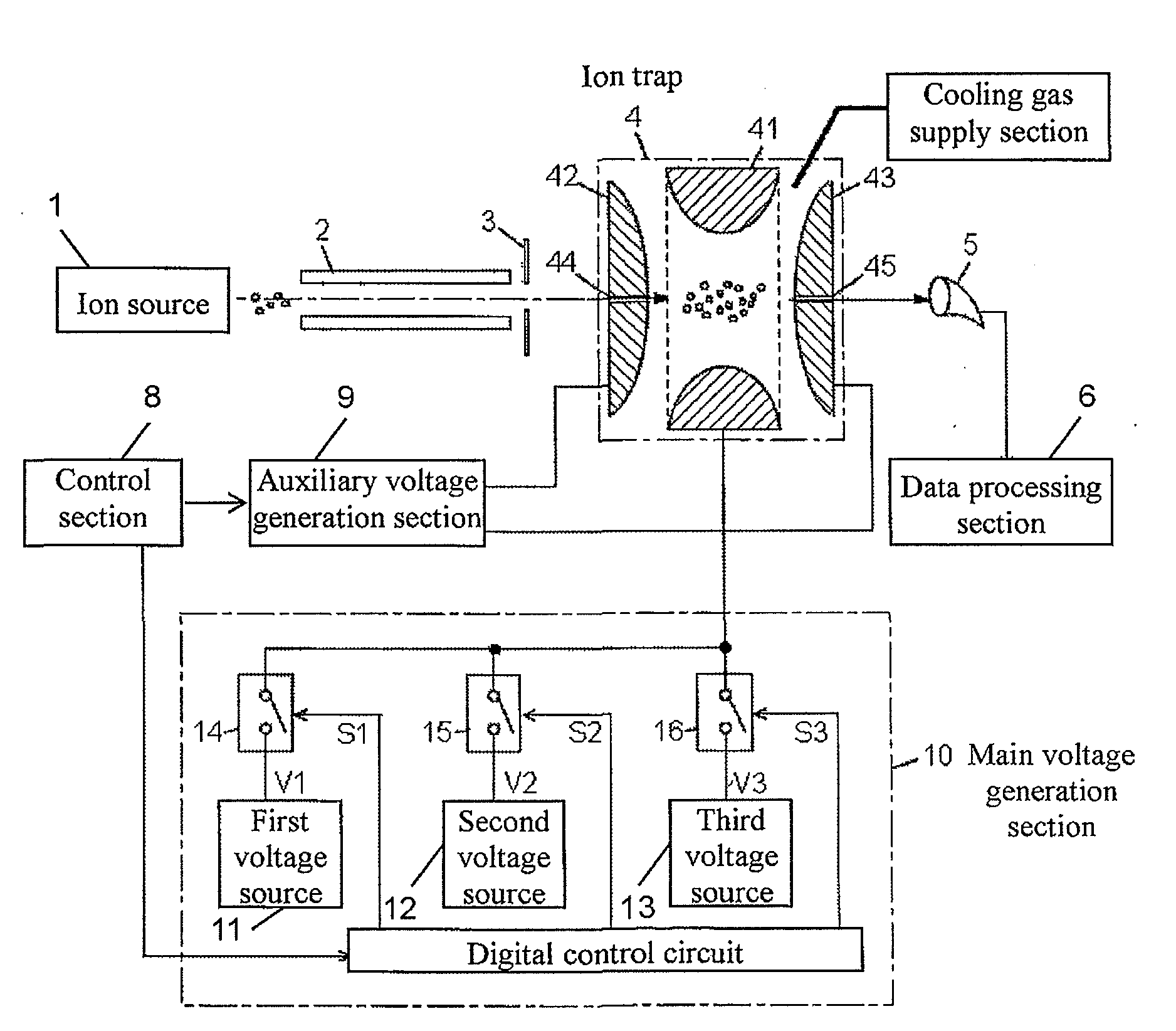
[0038]With reference to the drawings, an ion trap mass spectrometer according to one embodiment of the present invention will now be specifically described. FIG. 1 is a fragmentary block diagram showing the ion trap mass spectrometer according to this embodiment.

[0039]The ion trap mass spectrometer comprises an ion source 1, an ion transport optical system 2, a three-dimensional quadrupole ion trap 4, and an ion detector 5. In this embodiment, the ion source 1 is composed of an atmospheric pressure matrix-associated laser desorption / ionization (AP-MALDI) source. Alternatively, the ion source 1 may be composed of another type of atmospheric pressure ion source, or may be composed of an ion source operable to perform ionization under a vacuum atmosphere, instead of under an atmospheric pressure. Ions produced under an atmospheric pressure by the ion source 1 are introduced into a vacuum atmosphere by the configuration of a differential pumping system (not shown), and transported throu...


PUM


Abstract

The number of times of repetition of mass spectrometry analysis for integrating mass profiles is reduced to facilitate reduction in measurement time-period and increase a signal intensity. In a state when ions are trapped by a high-frequency electric field formed within an ion trap, a rectangular-wave high-frequency voltage to be applied from a main voltage generation section to a ring electrode is temporarily stopped, and next ions are introduced from an ion entrance port into the ion trap in a state when only a static electric field exists within the ion trap. The high-frequency voltage application is re-started while at least a part of previously-trapped ions remain within the ion trap, to trap the newly-introduced ions in addition to the previous ions so as to increase an amount of ions to be accumulated, and the accumulated ions are subjected to the mass spectrometry analysis.

Description

BACKGROUND ART[0001]1. Technical Field[0002]The present invention relates to an ion trap mass spectrometer comprising an ion trap operable to confine ions therein by an action of a high-frequency electric field.[0003]2. Description of the Related Art[0004]In late years, an ion trap mass spectrometer utilizing a three-dimensional quadrupole ion trap has been widely used as a highly-sensitive mass spectrometer. Typically, the three-dimensional quadrupole ion trap comprises one ring electrode having an inner surface in the shape of a hyperboloid of revolution of one sheet, and a pair of endcap electrodes disposed in opposed relation to each other across the ring electrode to have inner surfaces in the shape of a hyperboloid of revolution of two sheets.[0005]In addition to the above ion trap, a basic configuration of the ion trap mass spectrometer includes an ion source operable to ionize a target substance to be measured, an ion transport optical system operable to transport ions produ...

Claims


Application Information

Patent Timeline
Patent Type & Authority Applications(United States)
IPC IPC(8): H01J49/42
CPCH01J49/42
Inventor TAKESHITA, KENGOOGAWA, KIYOSHI
Owner SHIMADZU CORP
Why Eureka
Try Eureka