
Metallized plastic film and film capacitor

a technology of metallized plastic film and film capacitor, which is applied in the direction of wound capacitors, fixed capacitors, fixed capacitor details, etc., can solve the problems of deterioration of capacitor performance, large volume, and high cost, so as to reduce the rate of capacitance reduction, prevent the deterioration of dielectric strength of films, and improve the electrical properties of films.

Active Publication Date: 2008-11-13
NUINTEK
View PDF4 Cites 26 Cited by
  • Summary
  • Abstract
  • Description
  • Claims
  • Application Information

AI Technical Summary

Benefits of technology

[0020]Therefore, the present invention has been made in view of the above problems, and it is an object of the present invention to provide a metallized plastic film and a film capacitor capable of improving electrical property thereof by preventing deterioration of dielectric strength of a film even at a high temperature, reducing the rate of capacitance reduction by restraining an operation of a fuse part, and improving safety, compactness and heat resistance for use at a high temperature, by being formed by winding two sheets of metallized plastic film as one group and structured in a manner that fuse parts formed between each pair of a split electrode and a non-split electrode, the fuse parts where a flow of electric current in a width direction of the metallized plastic film is the greatest, are arranged in two rows in a length direction to decentralize generation of heat, thereby preventing occurrence of a high-heat at any special part and maintaining a low temperature throughout the film capacitor, and in a manner that the fuse parts of each metallized plastic film are not focusedly arranged in the middle part of the film capacitor but spaced apart from each other so that the heat is not focused to the fuse parts by a bottleneck situation but can be decentralized, thereby preventing an increase of temperature at the fuse parts.

Problems solved by technology

However, the above film capacitor causes a large volume and a high cost since a dedicated safety device is built in the outer case to guarantee safety in use and be used even under a high voltage.
Also, when an inner voltage occurs, since the safety device is operated, the performance of the capacitor is deteriorated.
As a result, performance of the fuse part 4 may not be stably maintained.
Consequently, the film capacitor cannot operate as desired.
However, this structure is also ineffective in guaranteeing the stable operation.
Accordingly, a withstanding voltage of the film capacitor is deteriorated, thereby restricting use of the film capacitor.
Therefore, safety of the film capacitor is not guaranteed.

Method used


Image

  • Metallized plastic film and film capacitor
  • Metallized plastic film and film capacitor
  • Metallized plastic film and film capacitor

Examples


first embodiment

[0061]In a metallized plastic film 130 according to the present invention as shown in FIG. 6a, the electrode metal is vapor-deposited on one or both sides of the dielectric plastic film 102, and the first splitting part 105 is continuously formed by cutting the vapor-deposited metal 103 by predetermined width and length along the length of the plastic film 102 on any one position within a range of ½˜⅘ of the width of the plastic film 102 from the margin part 101 formed at one side toward the other side with respect to the width of the plastic film 102. Accordingly, the first fuse part 104 is generated between every two first splitting parts 105.

[0062]The second splitting part 106 is formed by cutting the vapor-deposited metal 103 by predetermined width and length from the first splitting part 105 toward the margin part 101, thereby generating a split electrode 127 between two adjoining second splitting parts 106.

[0063]Additionally, the third splitting part 107 is formed by cutting t...

second embodiment

[0073]As a result, in the film capacitor as shown in FIG. 7a, just one first fuse part 104 and two second fuse parts 109 are provided so that the heat generation at the fuse parts can be reduced.

[0074]Furthermore, in a film capacitor formed by winding two sheets of the metallized plastic film 130 as one group, when the two sheets of metallized plastic film 130 are overlapped in the opposite directions as shown in FIG. 7b, the first fuse parts 104 where the flow of electric current in the width direction and the heat generation is greatest are arranged in two rows, thereby distributing the generated heat to two parts. Accordingly, occurrence of high heat in the middle of the film capacitor can be restrained and the film capacitor can be maintained at a relatively low temperature uniformly.

[0075]Consequently, the film capacitor can be used even under a high temperature state and have an improved lifespan.

[0076]Meanwhile, according to a third embodiment of the present invention as sho...
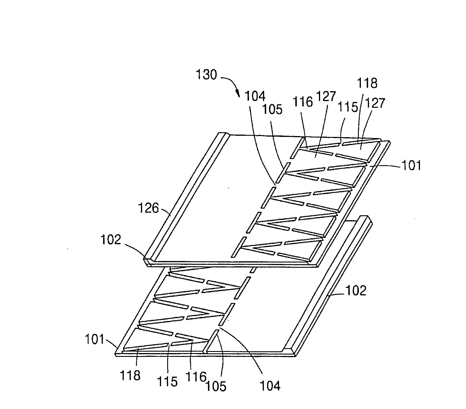
fourth embodiment

[0079]According to the present invention as shown in FIG. 9a, the electrode metal is vapor-deposited on one or both sides of the dielectric plastic film 102, the first splitting part 105 is continuously formed by cutting the vapor-deposited metal 103 by predetermined width and length along the length of the plastic film 102 on any one position within a range of ½˜⅘ of the width of the plastic film 102 from the margin part 101 formed at one side toward the other side opposite to the margin part 101 with respect to the width of the plastic film 102. Accordingly, the first fuse part 104 is generated between two adjoining first splitting parts 105.

[0080]The seventh splitting part 116 is formed by cutting the vapor-deposit 103 according to a pattern ‘>’ widening toward the margin part 101 so that a fifth fuse part 115 is formed in the middle position between the first splitting part 105 and the end of the vapor-deposited metal 103 near the margin part 101. Additionally, the eighth splitt...


PUM

PropertyMeasurementUnit
Widthaaaaaaaaaa
Widthaaaaaaaaaa
Surface resistanceaaaaaaaaaa

Abstract

A metallized plastic film is formed by winding two sheets of film vapor-deposited with an electrode metal as one group and a film capacitor, comprising; three individual splittings of electrode metal by predetermined width and length and then adjoining of splitting parts. Accordingly, self-heating of the film capacitor can be restrained and a capacitance reduction rate caused by the operation of the fuse parts can be reduced.

Description

BACKGROUND OF THE INVENTION[0001]1. Field of the Invention[0002]The present invention relates to a winding-type or laminated-type metallized plastic film and a film capacitor. More particularly, the present invention relates to a metallized plastic film and a film capacitor, improved in electrical property and safety of a film capacitor by restricting self-heating of the film capacitor and decreasing capacitance reduction rate caused by the operation of a fuse part and also improved in compactness and thermal resistance for use even at a high temperature.[0003]2. Description of the Related Art[0004]In general, electric capacitors, low-voltage power capacitors, electronic capacitors and so on are used in various fields of industry. Such capacitors usually adopt, as a dielectric, a plastic film which is made of polyethylene terephthalate resin, polypropylene resin, polyethylene naphthalate resin, polycarbonate resin or the like. To provide electrodes in those capacitors, a metallized ...

Claims


Application Information

Patent Timeline
IPC IPC(8): H01G4/08B32B15/08
CPCH01G2/16Y10T428/24917H01G4/32H01G4/015
Inventor YANG, CHANG HOONPARK, DAE JINJUN, YONG WON
Owner NUINTEK
Features
  • Generate Ideas
  • Intellectual Property
  • Life Sciences
  • Materials
  • Tech Scout
  • Unparalleled Data Quality
  • Higher Quality Content
  • 60% Fewer Hallucinations
Learn More