Lighting device and lighting method

Active Publication Date: 2008-11-13
IDEAL IND LIGHTING LLC
View PDF51 Cites 117 Cited by
  • Summary
  • Abstract
  • Description
  • Claims
  • Application Information

AI Technical Summary

Benefits of technology

[0104]The chromaticity coordinates (i.e., color points) that lie along the blackbody locus obey Planck's equation: E(λ)=Aλ−5/(e(B/T)−1), where E is the emission intensity, λ is the emission wavelength, T the color temperature of the blackbody and A and B are constants. Color coordinates that lie on or near the blackbody locus yield pleasing white light to a human observer. The 1976 CIE Diagram includes temperature listings along the blackbody locus. These temperature listings show the color path of a b

Problems solved by technology

It is well-known that incandescent light bulbs are very energy-inefficient light sources—about ninety percent of the electricity they consume is released as heat rather than light.
Fluorescent light bulbs are more efficient than incandescent light bulbs (by a factor of about ten) but are still less efficient than solid state light emitters, such as light emitting diodes.
In addition, as compared to the normal lifetimes of solid state light emitters, incandescent light bulbs have relatively short lifetimes, i.e., typically about 750-1000 hours.
Fluorescent bulbs have longer lifetimes (e.g., 10,000-20,000 hours) than incandescent lights, but provide less favorable color reproduction.
Another issue faced by conventional light fixtures is the need to periodically replace the lighting devices

Method used


Image

  • Lighting device and lighting method
  • Lighting device and lighting method
  • Lighting device and lighting method

Examples


first embodiment

[0195]FIG. 4 depicts a lighting device in accordance with the present inventive subject matter.

[0196]Referring to FIG. 4, there is shown a lighting device 10 which includes a heat spreading element 11 (formed of aluminum), insulating regions 12 (comprising any desired material which is thermally conductive and not electrically conductive, a wide variety of which are well-known to those skilled in the art, e.g., ceramic, epoxy or silicone optionally filled with silicon carbide, diamond, cubic boron nitride, alumina, etc), a highly reflective surface 13 (formed in situ by polishing the surface of the aluminum heat spreading element, or made of MCPET® (marketed by Furukawa, a Japanese corporation)), conductive traces 14 formed of copper, lead frames 15 formed of silver-plated copper (or silver-plated mild steel), a packaged LED 45 (described in more detail below), a reflective cone 17 (made of MCPET®) with a diffuse light scattering surface and a diffusing element 18 (the diffusing ele...

second embodiment

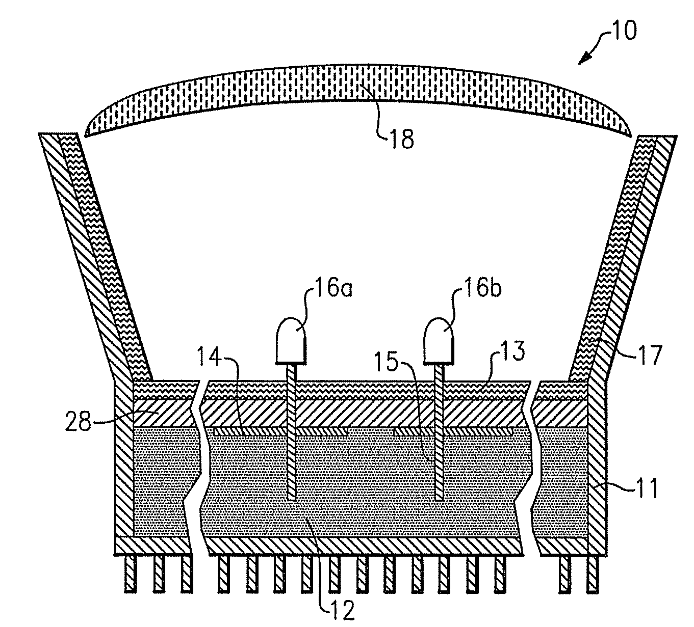
[0200]FIG. 6 depicts a lighting device in accordance with the present inventive subject matter. The device depicted in FIG. 6 includes a first packaged LED 16a and a second packaged LED 16b. The first packaged LED 16a (depicted in FIG. 7) includes an LED chip 31 and a lumiphor 35a. The LED chip 31, when illuminated, emits light having a peak wavelength in the near ultraviolet range. The first lumiphor 35a, when excited, emits light having a dominant wavelength in the range of from about 480 nm to about 490 nm. The second packaged LED 16b is similar to the first packaged LED 16a, except that instead of the first lumiphor 35a, the second packaged LED 16b includes a lumiphor which, when excited, emits light having a dominant wavelength in the range of from about 580 nm to about 590 nm.

third embodiment

[0201]FIG. 8 depicts a lighting device in accordance with the present inventive subject matter. The device depicted in FIG. 8 includes a packaged LED 16c. The packaged LED 16c is similar to the packaged LED 16a, except that instead of the first lumiphor 35a, the packaged LED 16c includes a lumiphor which contains a mixture of luminescent material which, when excited, emits light having a dominant wavelength in the range of from about 480 nm to about 490 nm and luminescent material which, when excited, emits light having a dominant wavelength in the range of from about 580 nm to about 590 nm

[0202]A fourth embodiment of a lighting device in accordance with the present inventive subject matter is similar to the device depicted in FIG. 6, except that instead of the first packaged LED 16a, the fourth embodiment includes a packaged LED 16b which includes (1) an LED chip which, when illuminated, emits light having a peak wavelength in the near ultraviolet range and (2) a lumiphor which, wh...


PUM


Abstract

A lighting device comprising one or more solid state light emitters which emit near ultraviolet light or ultraviolet light, one or more other emitters which emit light in the range of 480 nm to about 490 nm and one or more other emitters which emit light in the range of 580 nm to about 590 nm, to make a mixture which in the absence of any other light would have a combined illumination which is within twenty MacAdam ellipses of at least one point on the blackbody locus on a 1931 CIE Chromaticity Diagram. One or more of the other emitters is a lumiphor. One or more of the other emitters can be a solid state light emitter. Also, packaged solid state light emitters and methods of lighting.

Description

CROSS-REFERENCE TO RELATED APPLICATIONS[0001]This application claims the benefit of U.S. Provisional Patent Application No. 60 / 916,590, filed May 8, 2007, the entirety of which is incorporated herein by reference.FIELD OF THE INVENTION(S)[0002]The present inventive subject matter relates to a lighting device, in particular, a device which includes one or more solid state light emitters (e.g., light emitting diodes) and one or more luminescent materials (e.g., one or more phosphors). The present inventive subject matter is also directed to a packaged solid state light emitter. The present inventive subject matter is also directed to lighting methods.BACKGROUND OF THE INVENTION(S)[0003]A large proportion (some estimates are as high as twenty-five percent) of the electricity generated in the United States each year goes to lighting. Accordingly, there is an ongoing need to provide lighting which is more energy-efficient. It is well-known that incandescent light bulbs are very energy-in...

Claims


Application Information

Patent Timeline
IPC IPC(8): F21V9/00F21V9/16F21K99/00H01L33/50
CPCF21K9/00F21Y2101/02H01L33/504H01L33/507H01L2224/48247Y10S362/80H01L2224/48091H01L2924/13091H01L2924/00014H01L2924/00F21K9/62F21Y2115/10
Inventor VAN DE VEN, ANTONY PAULNEGLEY, GERALD H.
Owner IDEAL IND LIGHTING LLC
Why Eureka
Try Eureka