Method for Manufacturing Chalcopyrite Thin-Film Solar Cell

a technology of chalcopyrite and thin film, which is applied in the direction of final product manufacturing, sustainable manufacturing/processing, pv power plants, etc., can solve the problems of slight adhesion unevenness of alkali-metal-containing aqueous solution to the electrode layer, stain spots on the surface, and decrease in adhesion between the two layers, so as to improve the photoelectric conversion efficiency of the solar cell and improve the external appearance.

Inactive Publication Date: 2008-11-20
HONDA MOTOR CO LTD
View PDF1 Cites 79 Cited by
  • Summary
  • Abstract
  • Description
  • Claims
  • Application Information

AI Technical Summary

Benefits of technology

[0037]In the method for fabricating a chalcopyrite-type thin-film solar cell according to the present invention, in order to form a light absorbing layer, a precursor comprising a component which contains In, Cu and Ga metallic elements is formed, an alkali-metal solution is attached to the precursor, and an alkali component is attached to the precursor on a side opposite to the backside electrode layer. Subsequently, a heat treatment is carried out in a hydrogen selenide gas atmosphere. At this stage, CIGS crystal growth is suppressed at the electrode layer side of the precursor layer. Furthermore, even when the concentration of the alkali-metal solution is comparatively high, a stable layered inter-layer structure which does not change much over time can be obtained, and defects in external appearance from the manifestation of stain spots are less likely to occur.
[0038]In addition, an improvement in photoelectric conversion efficiency of a solar cell can be achieved by appropriately varying the concentration of the alkali-metal solution used as the alkali layer forming raw material depending on the alkali metal content of the substrate material, which may be an alkali-containing glass, a low-alkali glass or the like.

Problems solved by technology

Specifically, it is thought that excessive growth of the CIGS crystal particles causes localized stress concentration at the boundary between the electrode layer and the light absorbing layer, thereby resulting in a decrease in adhesion between the two layers.
It is also thought that slight adhesion unevenness of the alkali-metal-containing aqueous solution to the electrode layer develops into stain spots on the surface of the thin-film solar cell, through excessively grown crystal particles.

Method used


Image

  • Method for Manufacturing Chalcopyrite Thin-Film Solar Cell
  • Method for Manufacturing Chalcopyrite Thin-Film Solar Cell
  • Method for Manufacturing Chalcopyrite Thin-Film Solar Cell

Examples


example 1

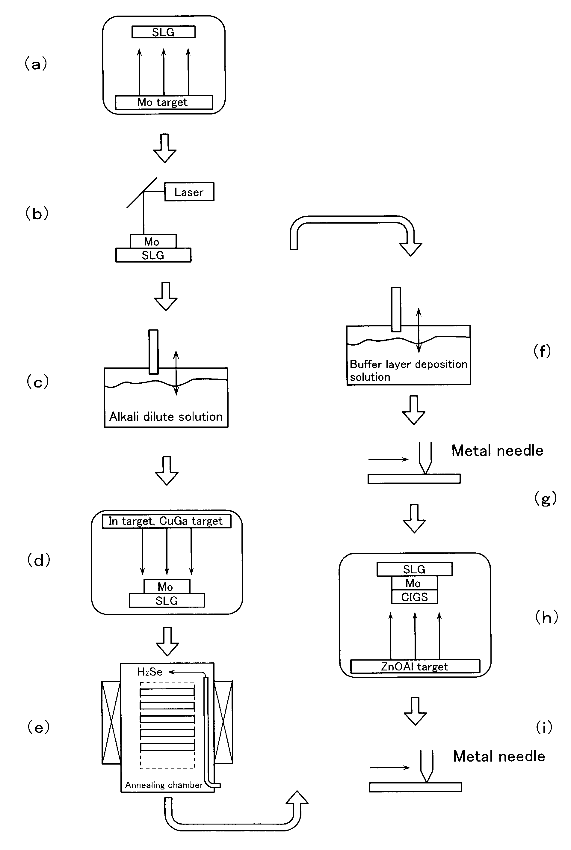
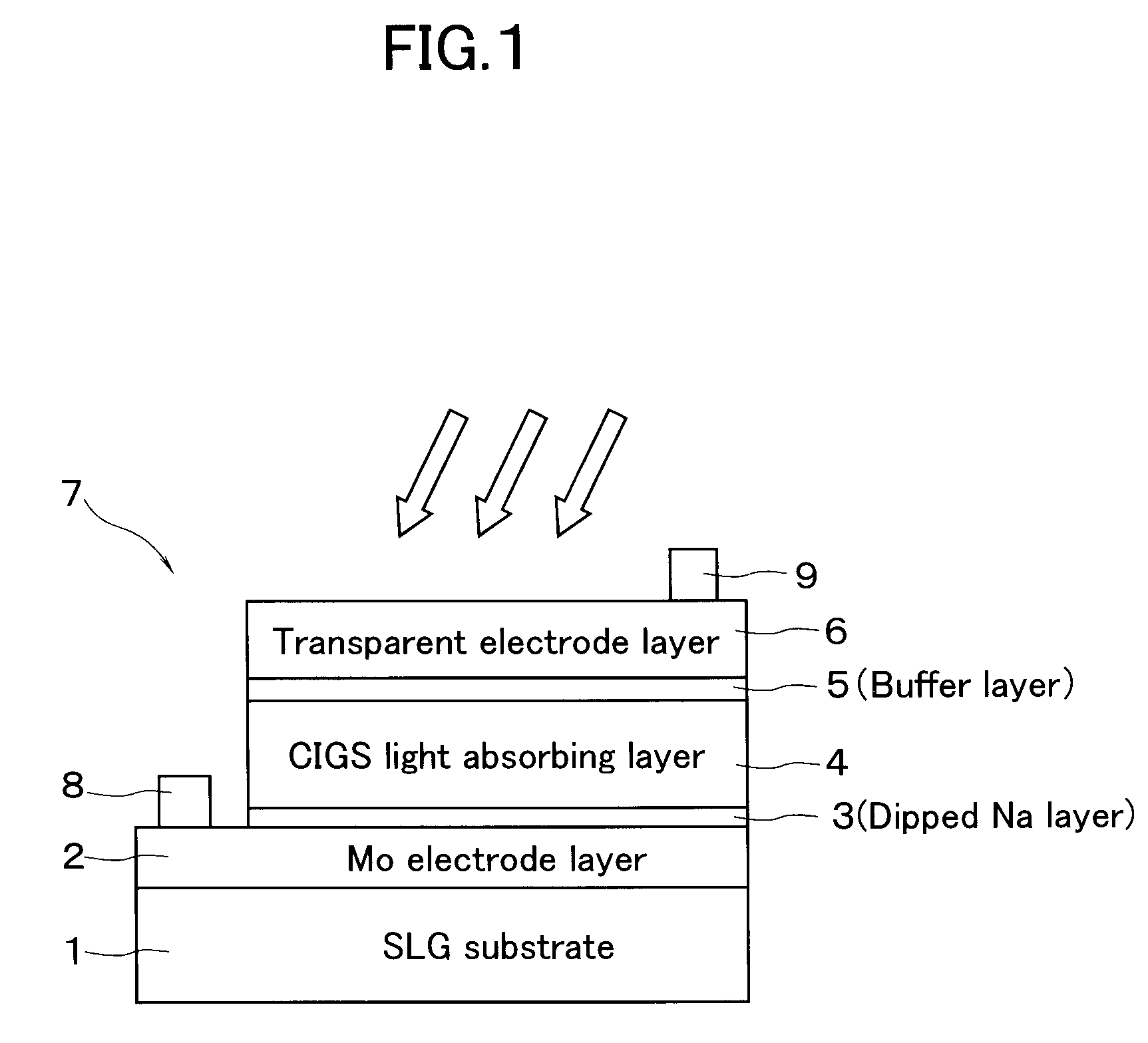
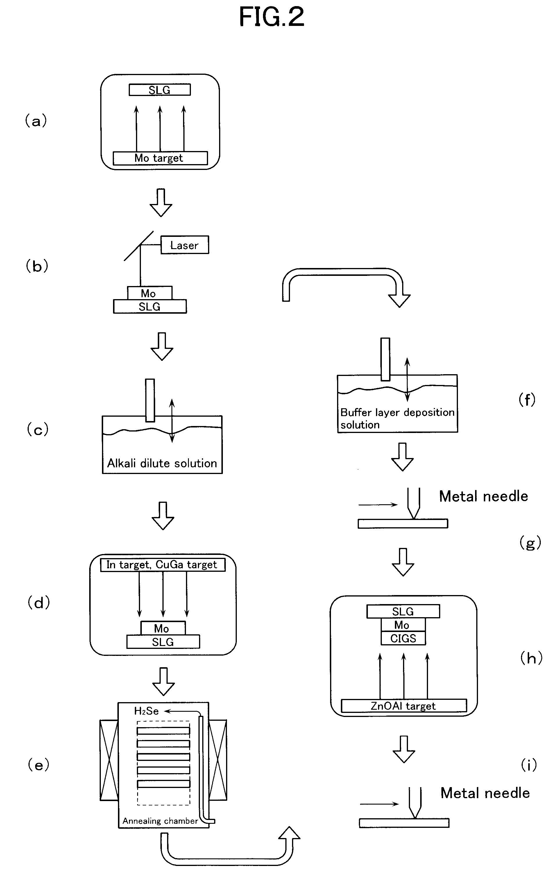
[0077]Using the inline sputter deposition apparatus illustrated in FIG. 4, a layered precursor consisting of an In metal layer and a Cu—Ga alloy layer was formed on an SLG substrate. Next, the SLG substrate on which the precursor had been deposited was dipped into a 0.8% by weight aqueous solution obtained by dissolving sodium tetraborate decahydrate in pure water, and the attached aqueous solution was then dried by a spin-drying method. After this, a selenization treatment was carried out in accordance with the temperature profile illustrated in FIG. 6 using the heat-treatment apparatus illustrated in FIG. 5.

[0078]Onto the thus formed light absorbing layer, a buffer layer and a conductive transparent electrode layer were deposited in that order, to thereby fabricate a thin-film solar cell. This thin-film solar cell had a stable film internal structure, and exhibited an external appearance free from stain spots. Measurement of the photoelectric conversion efficiency for 8 thin-film ...

examples 2 and 3

[0079]A thin-film solar cell was fabricated under the same conditions as in Example 1, except that the concentration of sodium tetraborate was changed to 1.6% by weight and 2.4% by weight, respectively. These thin-film solar cells had a stable film internal structure, and exhibited an external appearance free from stain spots. Measurement of the respective photoelectric conversion efficiencies for 8 thin-film solar cells fabricated under the same conditions gave, as illustrated in FIG. 8, a photoelectric conversion efficiency of 10.66% and 11.05%.

example 4

[0084]A thin-film solar cell article was fabricated under the same conditions as in Example 1, except that the substrate was changed to a low-alkali glass, such as white sheet glass. At this time, by making various changes to the concentration of sodium tetraborate forming the alkali layer, high respective photoelectric conversion efficiency was exhibited when the concentration was from 3.2 to 4.3% by weight.

[0085]Since the substrate material was a low-alkali glass, the alkali component supplied from diffusion into the light absorbing layer from the substrate was insufficient. However, such a high photoelectric conversion efficiency was attained since the highly concentrated aqueous sodium tetraborate supplemented it.

[0086]Consequently, photoelectric conversion efficiency can be improved comparatively easily by appropriately varying the concentration of an alkali-metal solution, which forms the alkali layer, depending on the substrate material, which may be alkali-containing glass, ...


PUM

PropertyMeasurementUnit
temperatureaaaaaaaaaa
diameteraaaaaaaaaa
pressureaaaaaaaaaa

Abstract

A method for fabricating a chalcopyrite-type thin film solar cell includes a first step of forming onto a Mo electrode layer 2 a precursor including an In metal layer and a Cu—Ga alloy layer by sputtering, a second step of attaching an alkali-metal solution onto the precursor, a selenization step of subjecting the substrate 1 which has undergone both the first and the second steps to a selenization treatment, and a transparent electrode forming step of depositing an optically transparent conductive layer. As the alkali-metal solution, an aqueous solution of an alkali metal compound, such as sodium tetraborate, sodium sulfide, and sodium aluminum sulfate, can be used.

Description

TECHNICAL FIELD[0001]The present invention relates to a method for fabricating a chalcopyrite-type thin-film solar cell whose light absorbing layer comprises a chalcopyrite-type compound layer.BACKGROUND ART[0002]Solar cells can be broadly classified into types which include silicon solar cells, thin-film solar cells and compound solar cells. Among these, progress is being made in the commercial development of thin-film solar cells as an optical device applying thin-film technology due to the advantages that their fabrication process is simple and does not require much energy. Chalcopyrite-type thin-film solar cells are categorized as thin-film cells, and comprise a CIGS layer consisting of a chalcopyrite-type compound (Cu(In+Ga)Se2: CIGS) as a p-type light absorbing layer. By using a light absorbing layer formed with such a compound, and in particular when employed together with an alkali-metal-containing glass substrate, such as soda lime glass, it is known that the solar cell can...

Claims


Application Information

Patent Timeline
Patent Type & Authority Applications(United States)
IPC IPC(8): C23C14/00H01L31/032
CPCH01L31/0322Y02E10/541Y02P70/50
Inventor AOKI, SATOSHI
Owner HONDA MOTOR CO LTD
Why Eureka
Try Eureka