Optical characteristic measuring apparatus and measuring method using light reflected from object to be measured

a technology of optical characteristic and measuring apparatus, which is applied in the direction of optical radiation measurement, reflective surface testing, therapy, etc., can solve the problems of limited improvement of optical characteristic measurement precision, decreased light intensity (quantity of light) per unit area of illuminating light, and difficulty in directly obtaining an illuminating light having a wide wavelength band. , to achieve the effect of facilitating the focusing on the object to be measured and improving the accuracy of optical characteristic measuremen

Inactive Publication Date: 2008-11-20
OTSUKA DENSHI CO LTD
View PDF10 Cites 22 Cited by
  • Summary
  • Abstract
  • Description
  • Claims
  • Application Information

AI Technical Summary

Benefits of technology

[0010]The present invention has been made for solving the problems as described above. An object of the invention is to provide an optical characteristic measuring apparatus and an o

Problems solved by technology

However, it is difficult to directly obtain an illuminating light having a wide wavelength band, being stable and having a relatively large beam diameter.
An expanded beam diameter, however, results in a decreased light intensity (quantity of light) per unit

Method used


Image

  • Optical characteristic measuring apparatus and measuring method using light reflected from object to be measured
  • Optical characteristic measuring apparatus and measuring method using light reflected from object to be measured
  • Optical characteristic measuring apparatus and measuring method using light reflected from object to be measured

Examples


first embodiment

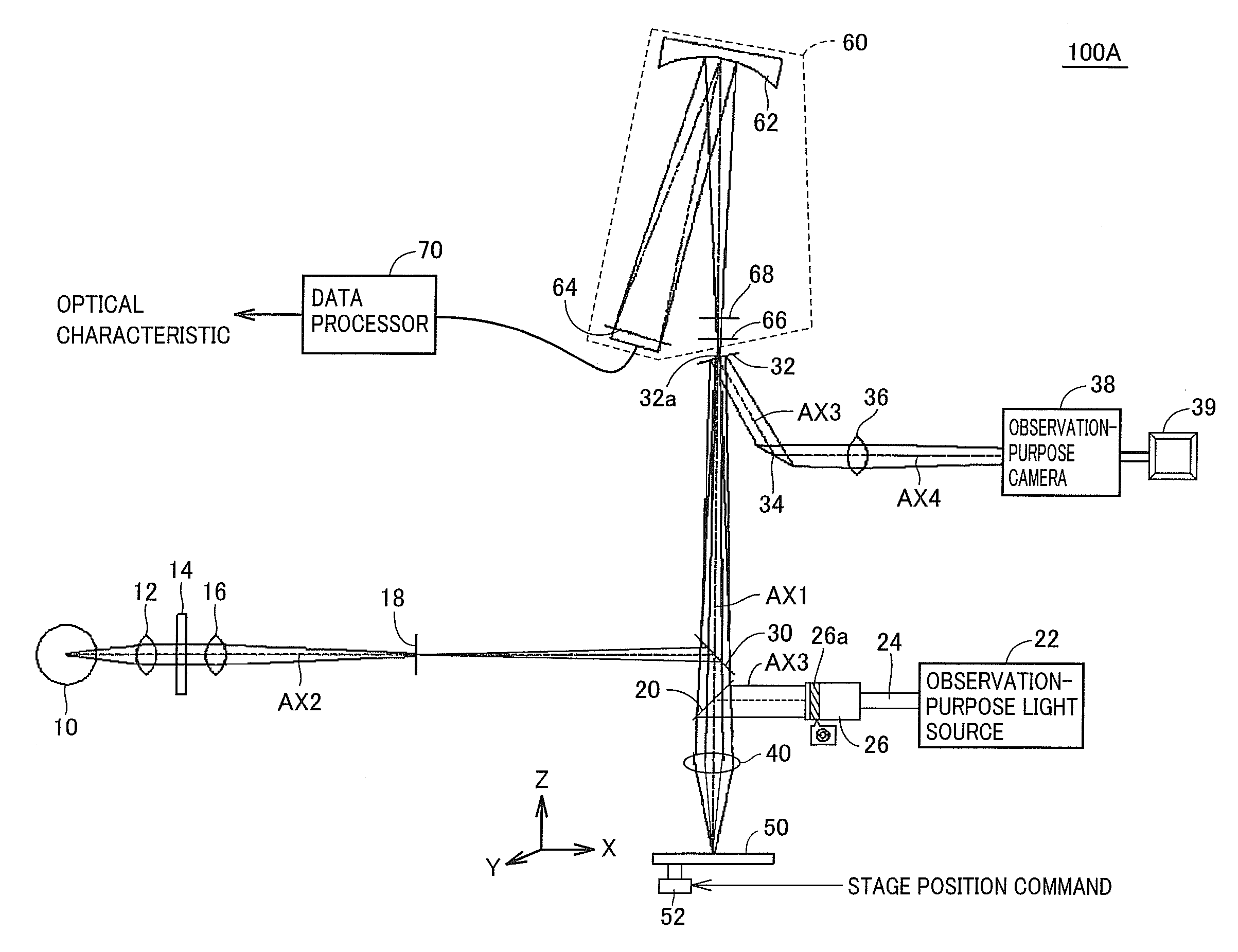
[0038]An optical characteristic measuring apparatus 100A according to a first embodiment of the present invention is typically a microspectroscopic measuring apparatus, and measures the spectrum of light reflected from an object to be measured (hereinafter also referred to as “object under measurement”), thereby measuring optical characteristics (optical constants) such as (absolute and / or relative) reflectance, refractive index, extinction coefficient, and film thickness of a thin film or the like formed on the object under measurement.

[0039]Typical examples of the object under measurement include a device with a thin film formed on any materials such as semiconductor substrate, glass substrate, sapphire substrate, quartz substrate, and film. More specifically, the glass substrate having the thin film formed thereon is used as a display unit of a flat panel display (FPD) such as liquid crystal display (LCD) or plasma display panel (PDP). Further, the sapphire substrate having the t...

second embodiment

[0089]Regarding optical characteristic measuring apparatus 100A in the first embodiment of the present invention, the configuration using the refractive lens as the objective lens is described as an example. Depending on the type of the object under measurement, however, a reflected light from the rear surface of the object under measurement could appear as a stray light to deteriorate the precision in measurement, despite the fact that the focus is adjusted on the front surface of the object under measurement. In such a case, preferably a reflective objective lens as described below is used.

[0090]FIG. 5 is a schematic configuration diagram of an optical characteristic measuring apparatus 100B according to a second embodiment of the present invention.

[0091]Referring to FIG. 5, optical characteristic measuring apparatus 100B in the second embodiment of the present invention differs from optical characteristic measuring apparatus 100A shown in FIG. 1 in that a reflective objective len...

third embodiment

[0112]Regarding the optical characteristic measuring apparatus in the first or second embodiment of the invention as described above, the configuration is explained where beam splitter 20 is disposed on the propagation path of the reflected light (measurement reflected light and observation reflected light) to inject the observation light. The position where the observation light is injected, however, is any position as long as the position is present on an optical path from measurement-purpose light source 10 to objective lens 40 which constitutes a condensing optical system. Accordingly, regarding a third embodiment of the present invention, a description will be given of a configuration where an observation light is injected on an optical path from measurement-purpose light source 10 to beam splitter 30.

[0113]FIG. 12 is a schematic configuration diagram of an optical characteristic measuring apparatus 100C in the third embodiment of the present invention.

[0114]Referring to FIG. 1...


PUM


Abstract

A measurement-purpose light source generates a measurement light used for measuring an optical characteristic of an object to be measured, and the measurement light includes a component in a wavelength range for measurement of the optical characteristic of the object. An observation-purpose light source generates an observation light used for focusing on the object to be measured and checking a position of measurement. The observation light is selected such that the observation light includes a component that can be reflected from the object to be measured. The measurement light and the observation light are thus applied independently to the object to be measured, through a common objective lens, and accordingly improvement of the precision in measurement of the optical characteristic and facilitation of focusing on the object to be measured are achieved simultaneously.

Description

BACKGROUND OF THE INVENTION[0001]1. Field of the Invention[0002]The present invention relates to an optical characteristic measuring apparatus and a measuring method using the optical characteristic measuring apparatus, and more particularly to a technique of measuring an optical characteristic such as the reflectance of a thin film with a higher precision.[0003]2. Description of the Background Art[0004]A microspectroscope is known as a typical optical characteristic measuring apparatus for measuring optical characteristics (optical constants) such as the reflectance, refractive index, extinction coefficient, and film thickness of a thin film by applying light to the thin film formed on a substrate for example and spectroscopically measuring the light reflected therefrom.[0005]A conventional microspectroscope is configured for example as disclosed in FIG. 1 of Japanese Patent Laying-Open No. 11-230829. The microspectroscope includes an illuminating optical system directing an illumi...

Claims


Application Information

Patent Timeline
IPC IPC(8): G01J3/00G01N21/55G01B11/06G01M11/00G01N21/27
CPCG01M11/005G01N21/8422G01N21/55G01J1/00G01J1/02G01J3/02
Inventor OKAWAUCHI, MAKOTOMIZUGUCHI, TSUTOMUKAWAGUCHI, SHIRO
Owner OTSUKA DENSHI CO LTD
Why Eureka
Try Eureka