Geothermal heat exchanger

a heat exchanger and geothermal technology, applied in the field of heat exchangers, can solve the problems of reducing the efficiency of the condenser's ability to expunge heat from the refrigerant, and often being unable to meet the requirements of pumping and dumping systems, etc., to achieve better “slow crack resistance” and high pressure

Active Publication Date: 2008-11-27
G I PATENTS LLC
View PDF16 Cites 42 Cited by
  • Summary
  • Abstract
  • Description
  • Claims
  • Application Information

AI Technical Summary

Benefits of technology

[0037]In a first embodiment shown in FIGS. 1-9, the divider wall preferably includes a first wall portion and a second wall portion that define an air gap there between. The purpose of this air gap is to reduce heat transfer between fluid in the outflow and the inflow pipe portion.
[0042]One advantage of the use of the central grout dispensing passageway is that it permits a relatively smaller diameter heat exchanger pipe to be used, that thereby permits a smaller bore hole to be dug, which reduces the cost of the heat exchanger installation. Also, by reducing the thickness of the grout layer, one reduces the insulative influence of the grout, which thereby improves the transfer properties between the water flowing within the pipe and the surrounding ground. This serves to reduce the thermal resistance of the geothermal system.
[0044]The particular plastic that is preferred by Applicants has a bi-modal structure, rather than the unimodal structure that is commonly used in connection with known pipes of the prior art. This bi-modal structure results in a higher strength pipe, wherein a pipe of a given diameter is capable of withstanding much higher pressures than the unimodal pipe that it replaces. Additionally, the bi-modal structure results in better “slow crack resistance” and also better “rapid crack resistance”, which results in both a more rigid pipe and also a pipe that is less subject to failure. It is Applicants' belief that a bi-modal pipe is likely to have a longer and more problem resistant useful life than an unimodal pipe.
[0045]Additionally, the plastic used with the present invention permits the walls of the pipe to be made more thin. In addition to reducing the amount of material necessary to construct the pipe, the use of thinner walls enhances the thermal transfer between the water flowing within the interior of the pipe and exterior of the pipe including the grout and the surrounding ground.
[0046]The present invention is believed to have enhanced heat transfer capabilities, when compared to currently-existing pipes. These enhanced heat transfer capabilities, shown in FIG. 18, permit the user to achieve a level of heat transfer in a geothermal energy system, using a smaller length of pipe than with the prior art. By being able to achieve the same cooling capacity (e.g. 1 ton of cooling) with less pipe, the user can incur less boring costs because fewer feet of bore hole need be drilled, when compared with the prior art.

Problems solved by technology

Similarly, when used in an air-conditioning capacity during the summer, the heat of the outside air reduces the efficiency of the condenser's ability to expunge heat from the refrigerant during the compression of the refrigerant into liquid refrigerant by the compressor.
Unfortunately, steel and metal pipes are often unacceptable, because of their propensity to corrode, and hence fail over a reasonably short period of time.
These environmental concerns arise largely from the fact that many cities forbid the use of “pump and dump” geothermal systems.
Such pump and dump systems are forbidden in many locations because of the fact that they can pollute the ground water aquifer.
Unfortunately, the grout adversely impacts the heat transfer capabilities of the pipe.

Method used


Image

  • Geothermal heat exchanger
  • Geothermal heat exchanger
  • Geothermal heat exchanger

Examples


Embodiment Construction

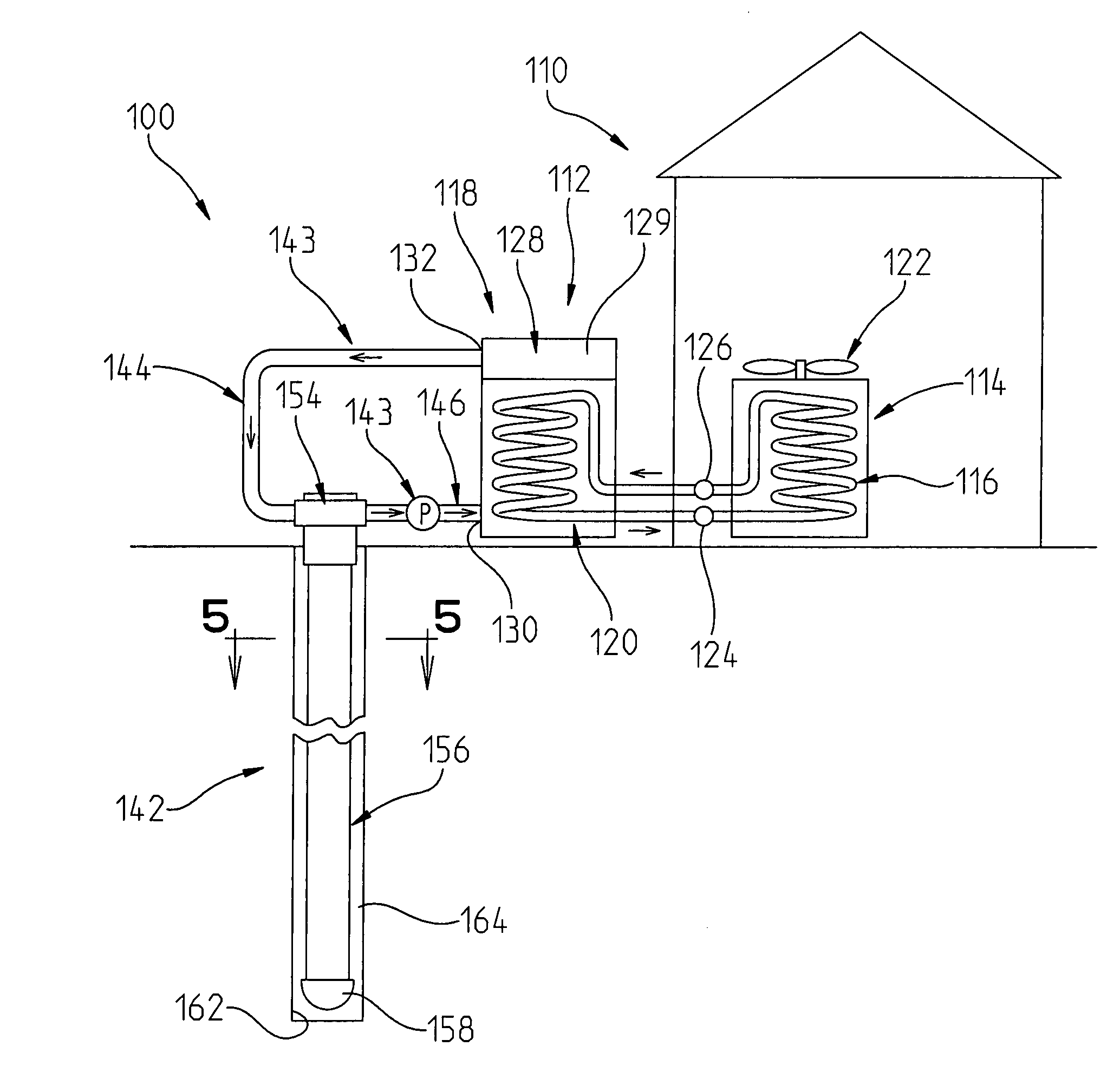
[0070]The geothermal heat exchange system 100 of the present invention is best shown in FIGS. 4-9. Turning first to FIG. 4, the geothermal heat exchange system 100 is shown schematically as being coupled to the mechanical refrigeration system 112 of a building 110.

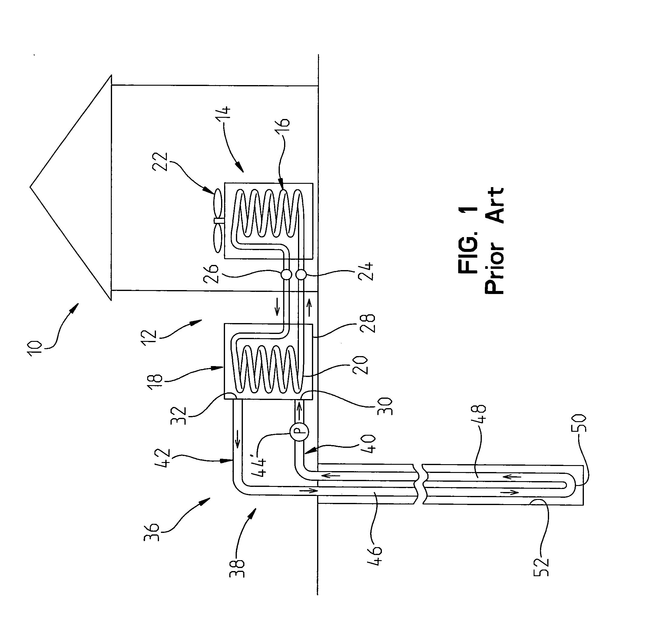
[0071]Generally, mechanical refrigeration system 112 and building 110 are similar to mechanical refrigeration system 12 for building 10 shown in FIG. 1. The mechanical refrigeration system 112 includes an inside (first) heat exchanger having a coil 116 through which refrigerant flows; and an outside (second) heat exchanger 118 having a coil 120 through which refrigerant flows, in the same closed loop as does the refrigerant flowing through the coil 116 of inside heat exchanger 114. A fan 122 is provided for causing air to flow across the coil 116 of the inside heat exchanger so that, during summer, the air can be cooled by its passage past the coil 116; and in the winter the air can be heated by its passage across the coil...


PUM


Abstract

A pipe for use in a geothermal heat exchange system is disclosed that is insertable into a bore hole having a proximal end and a distal end. The pipe has a proximal end, a distal end and an outer wall member. The outer wall member includes an external surface, and an interior surface defining an interior passageway through which a heat exchange fluid can flow. The pipe also includes a divider extending between opposed points of the interior surface for dividing the interior passageway into an inflow passageway for conducting water from the proximal end to the distal end of the pipe, and an outflow passageway for conducting water from the distal end to the proximal end of the pipe. The divider segregates the water in the outflow passageway from the water in the inflow passageway.

Description

I. PRIORITY CLAIM[0001]This application claims benefit of U.S. Provisional Patent Application No. 60 / 931,737 filed 25 May 2007, which provisional application is fully incorporated herein by reference.II. TECHNICAL FIELD OF THE INVENTION[0002]The present invention relates to a heat exchanger, and more particularly, to a heat exchanger that is especially well adapted for use in geothermal heating and cooling systems, as a thermal energy storage device.III. BACKGROUND OF THE INVENTION[0003]Geothermal heating and cooling systems typically employ water as a medium to absorb and retain heat. The water that passes through the geothermal heating piping system can be passed through a heat exchanger, to which a blower is attached to pass the air over the heat exchanger.[0004]The geothermal heating and cooling system obtains its ability to aid in the heating or cooling of a building by exploiting the general constancy of ground temperatures. A typical geothermal heating system comprises a clos...

Claims


Application Information

Patent Timeline
Patent Type & Authority Applications(United States)
IPC IPC(8): F24J3/08
CPCF24J3/083Y02E10/125F24T10/15F24T10/17Y02E10/10
Inventor HARDIN, JAMESZHANG, CHANGCHUN
Owner G I PATENTS LLC
Why Eureka
Try Eureka