Methods of Limiting Leak Off and Damage In Hydraulic Fractures

a hydraulic fracture and leakage prevention technology, applied in the direction of fluid removal, chemistry apparatus and processes, borehole/well accessories, etc., can solve the problems of high fluid loss, affecting fracture geometry, and implying a more expensive treatment, so as to improve cleanup and hydrocarbon production

Inactive Publication Date: 2008-11-27
SCHLUMBERGER TECH CORP
View PDF53 Cites 86 Cited by
  • Summary
  • Abstract
  • Description
  • Claims
  • Application Information

AI Technical Summary

Benefits of technology

[0015]In some embodiments, the water inert degradable polymer is functionalized in such a way that the polymer degrades after providing at least sufficient fluid loss in a fracture, thus resulting in enhanced cleanup and

Problems solved by technology

While a reduced fluid loss allows for a better efficiency of the treatment, a higher fluid loss corresponds to fluids “wasted” in the reservoir, and implies a more expensive treatment.
Furthermore fluid efficiency of a fracture fluid may affect fracture geometry, since the viscosity of the fluid might change as the fluid is lost in the formation.
For VES based fluids, excessive fluid loss results in fractures that are narrower than desired.
Also, excessive fluid loss may translate into significant job size where hundreds of thousands of additional gallons of water may be pumped to generate the required length of fracture and overcome low fluid efficiency.
However, as it became apparent that crosslinked polymer gel residues might not degrade completely and leave a proppant pack with an impaired retained conductivity, fluids with lower polymer content were introduced.
Nonetheless the polymer based fracturing treatments leave proppant pack with damaged retained conductivity since the polymer fluids concentrate in the fracture while the water leaks off in the reservoir

Method used


Image

  • Methods of Limiting Leak Off and Damage In Hydraulic Fractures
  • Methods of Limiting Leak Off and Damage In Hydraulic Fractures
  • Methods of Limiting Leak Off and Damage In Hydraulic Fractures

Examples


examples 1 through 3

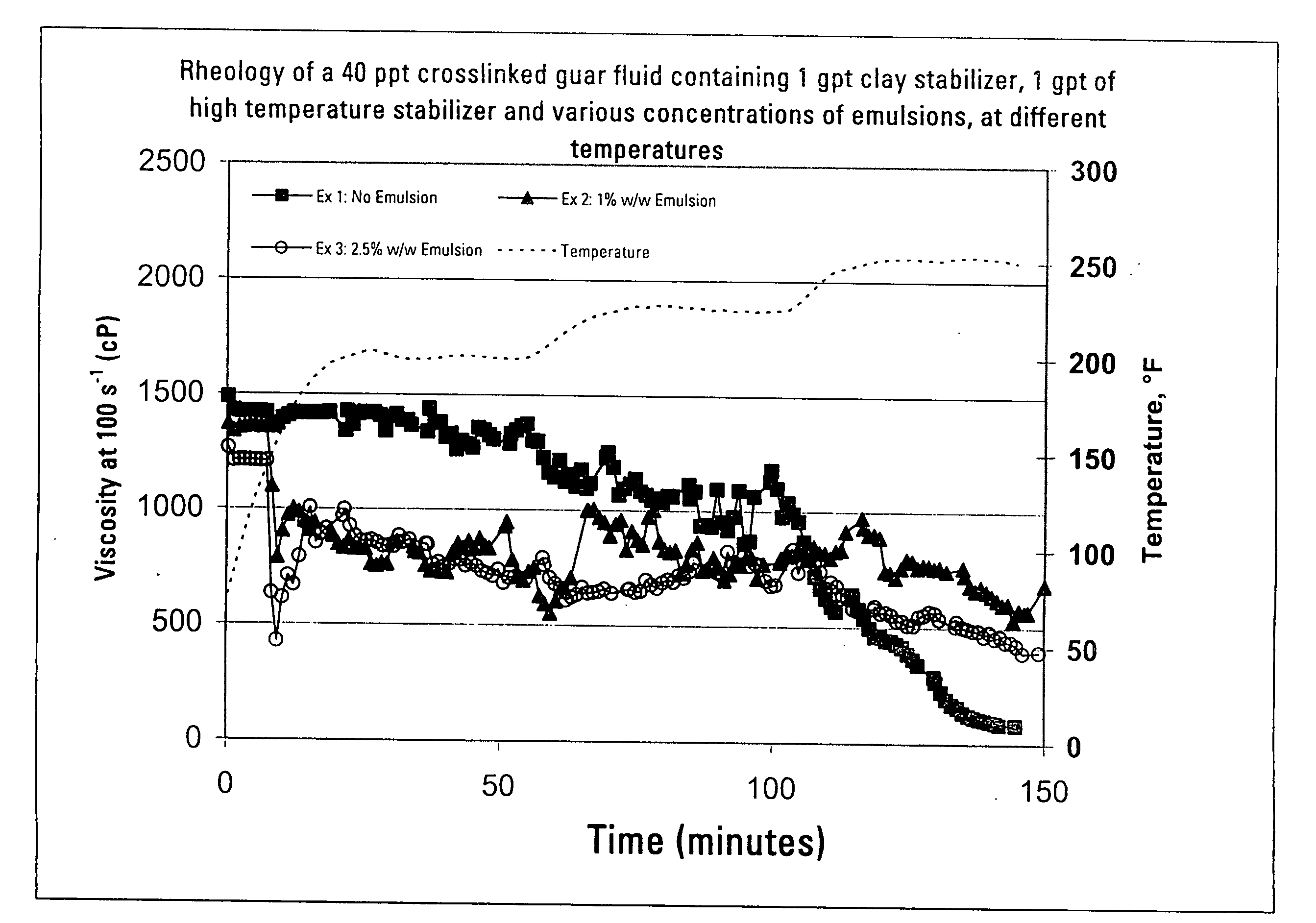
[0092]In these examples the water inert degradable polymer, in the form of an emulsion, is blended with a conventional fracturing fluid during early stages of the treatment (pad), and the rheology of the fluid with and without the water inert degradable polymer is compared to ensure that adequate viscosity is developed and maintained for fracturing. The pad fluid contained 40 ppt [4.8 kg / 1000 L] guar gum supplied by Economy Polymers and Chemicals, Houston, Tex. 77245-0246, the guar being crosslinked with a borate crosslinker (4 ppt [0.48 kg / 1000 L] of boric acid, with a pH adjusted to ˜11 using a 30% weight aqueous solution of caustic soda). The emulsion added was ChemCor PolyEMULSION 330N35. The graph in FIG. 1 shows the viscosity, measured using a conventional Fann 50 rheometer, of the pad fluid containing no emulsion (Example 1), 1% by weight of ChemCor HDPE PolyEMULSION 330N35 emulsion based upon total fluid weight (Example 2), and 2.5% by weight of ChemCor HDPE PolyEMULSION 330...

examples 4 through 7

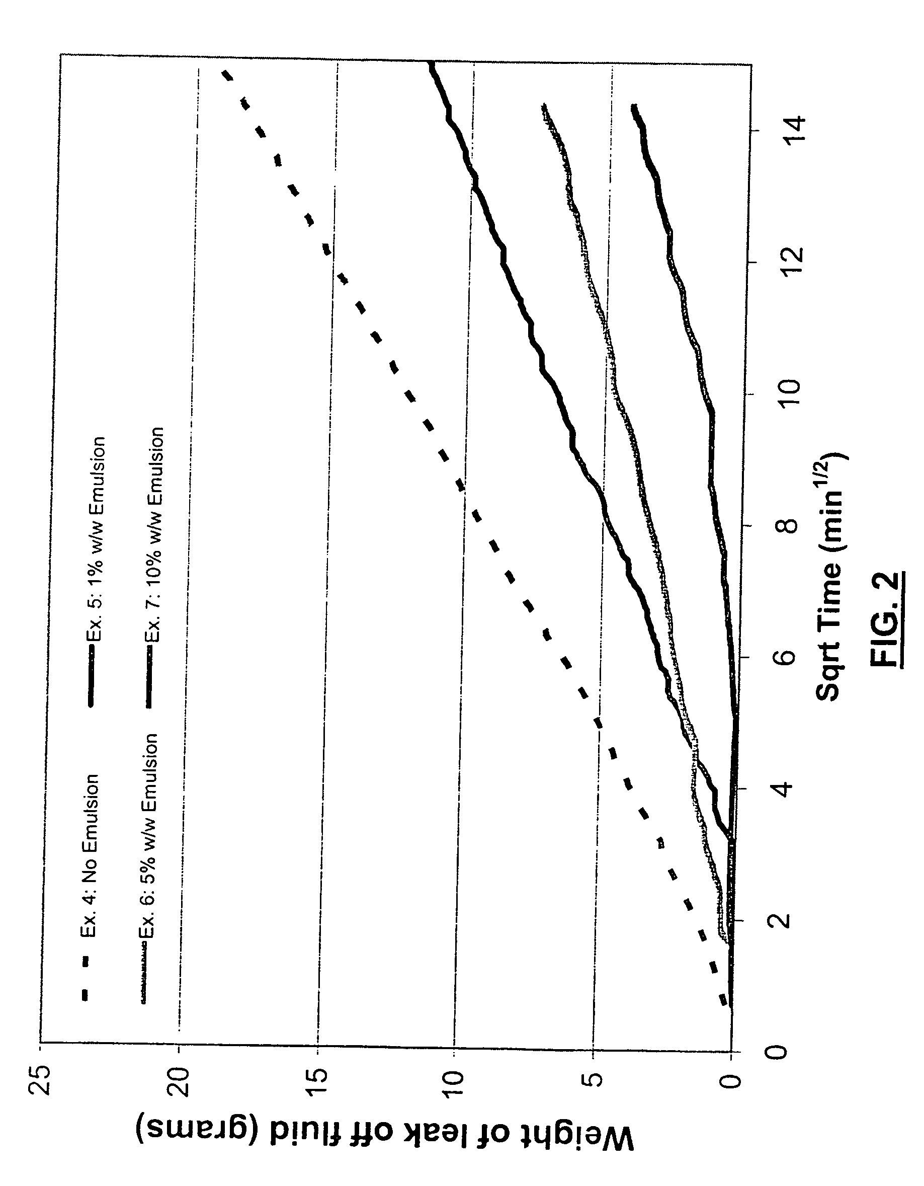
[0094]In examples 4 through 7, and referring to FIG. 2, the fluid loss is measured on samples with a water inert degradable polymer, in the form of an emulsion, blended with conventional fracturing pad fluids, and fluid loss is determined for the fluid with and without the water inert degradable polymer. The pad fluids contained 25 ppt [3 kg / 1000 L] guar gum supplied by Economy Polymers and Chemicals, the guar being crosslinked with a borate crosslinker (4 ppt 0.48 kg / 1000 L] of boric acid, with a pH adjusted to ˜11 with caustic soda). The pad fluid also included DI water, contained a 50% by weight aqueous solution of tetramethyl ammonium chloride clay stabilizer added at 2 gpt [Lpt], and 1 gpt [Lpt] of a 85% by weight solution of triethanol amine high temperature stabilizer. In examples 5 through 7, the emulsion added was ChemCor PolyEMULSION 330N35.

[0095]The fluids were evaluated on a static fluid loss cell using 1″ diameter cores of varied permeability at 175° F. [79.4° C.] with ...

examples 8 through 15

[0096]For examples 8 through 15, pad fluids, formulated in accordance with the pad fluids of examples 1 and 4 above, with and without either ChemCOR PolyEMULSION 330N35 or PolyEMULSION 629N40, were tested at different temperatures and normalized leak-off coefficients (Cw / sqrt(K)) determined and reported in FIG. 3. Cw is discussed in Navarrete, R. C., Caweizel, K. E., and Constien, V. G.: “Dynamic Fluid Loss in Hydraulic Fracturing Under Realistic Shear Conditions in High-Permeability Rocks,” SPE Production and Facilities, pp 138-143 (August, 1996). To determine leak-off rates, experiments were conducted in a conventional static fluid loss cell at 1200 psi [8.27 MPa] total pressure and a back pressure of 200 psi [1.38 MPa] back pressure, for a net pressure of 1000 psi [6.89 MPa. The core was held at constant temperature, as indicated in FIG. 3, and the fluid collected at the discharge of the core. The rate of fluid leaking off through the core was measured as a function of time. The ...


PUM


Abstract

Methods for treating a formation penetrated by a wellbore which improves fluid loss control during treatment. In some aspects, the treatments include preparing an aqueous fluid including one or more water inert degradable polymers and an optional viscosifier, injecting the aqueous fluid into the wellbore at a pressure equal to or greater than the formation's fracture initiation pressure, and thereafter injecting into the wellbore a proppant laden fluid at a pressure equal to or greater than the formation's fracture initiation pressure. The water inert degradable polymer may be a polymer such as an emulsion polymer or a latex polymer. Some methods of the invention use a fluid which may have a normalized leak off coefficient (Cw/sqrt(K)) equal to or less than about 0.0022, 0.0014, or 0.0010. A conventional fluid loss additive may or may not be used in conjunction with the treatment fluid and/or the proppant laden fluid. The water inert degradable polymer may or may not substantially enter formation pores. In another aspect, methods for reducing matrix damage to a formation during a treatment operation include preparing an aqueous treatment fluid formed of at least one water inert degradable polymer, and injecting the fluid at a pressure equal or greater than the formation's fracture initiation pressure.

Description

TECHNICAL FIELD OF THE INVENTION[0001]This application is a Continuation-In-Part Application of, claims priority to, and the benefit of U.S. patent application Ser. No. 11 / 532,705 filed Sep. 18, 2006.TECHNICAL FIELD OF THE INVENTION[0002]This invention relates to improving the production of fluids from wells penetrating subterranean formations. More particularly, this invention relates to methods using stabilized aqueous dispersions of water inert degradable polymers in treatment fluids to improve fluid efficiency during hydraulic fracture treatments while minimizing or preventing proppant pack damage.BACKGROUND OF THE INVENTION[0003]Hydraulic fracturing of oil or gas wells is a technique routinely used to improve or stimulate the recovery of hydrocarbons. In such wells, hydraulic fracturing is usually accomplished by introducing a proppant-laden treatment fluid into a producing interval at high pressures and at high rates sufficient to crack the rock open. This fluid induces a frac...

Claims


Application Information

Patent Timeline
IPC IPC(8): E21B43/267
CPCC09K8/68C09K8/685C09K8/88C09K2208/26C09K2208/30
Inventor HUTCHINS, RICHARD D.LADVA, HEMANT K.WILLIAMSON, DONDANIEL, SYLVIE
Owner SCHLUMBERGER TECH CORP
Why Eureka
Try Eureka