Ice thickness measuring system

a technology of ice thickness and measuring system, which is applied in the direction of instruments, specific gravity measurement, digital computer details, etc., can solve the problems of ice sheets with substantially below the target range at risk of breaking apart, undetected high surface temperature of ice, unduly soft surface, etc., to enhance safety, increase the speed and accuracy of thickness measurement of ice sheets, the effect of enhancing the quality of the ice sh

Inactive Publication Date: 2008-12-04
PRECICE TECH
View PDF21 Cites 19 Cited by
  • Summary
  • Abstract
  • Description
  • Claims
  • Application Information

AI Technical Summary

Benefits of technology

[0014]The systems disclosed herein offer a non-destructive, ultrasonic thickness measurement of an ice sheet that is disposed on a solid or granular substrate, such as found in indoor ice arenas and outdoor skating and skating sport venues. The systems provide rink operators the ability to increase the speed and accuracy of thickness measurements of ice sheets for the enhancement of ice sheet quality, providing attendant benefits of enhanced safety and reduced labor and energy costs.

Problems solved by technology

An ice sheet with a thickness that is substantially below this target range is at risk to break apart, with the possible consequence of injuring participants or postponing, delaying or canceling an event.
As the thickness increases substantially above the targeted thickness, the surface temperature of the ice may become undesirably high due to the conductive temperature gradient through the ice thickness.
The skating surface may thereby become unduly soft and adversely affect the performance of participant skaters.
The temperature of an overly thick ice sheet may be brought into the preferred temperature range by further sub-cooling the ice sheet, but this requires additional expenditure in refrigeration costs.
The procedure is time consuming and labor intensive, and prone to the errors from a variety of sources including drilling the hole too deep (inadvertent penetration of the substrate) or not deep enough (sensing compacted ice rather than concrete), erroneously marking the drill bit, misreading of the tape or ruler, and the erroneous recording of the thickness measurement.
Furthermore, in some instances the hole may cause local stress gradients that may cause the ice surface to pock under the rigors of use, thereby causing a hazard.
Moreover, the marked drill bit technique is not readily applicable to all ice facilities.
For the second configuration, the operator cannot reliably detect when the ice sheet has been penetrated.
For the third configuration, even where a floor of sufficient hardness is implemented, there is a danger of damaging the refrigeration piping.
However, subsequent measurements are limited, and inspection of thickness in areas away from the pre-selected locations cannot be performed.
Kiode's measurement technique involves the measurement multiple reflections back and forth through the medium resulting from a single pulsed input, and is not well suited for configurations where the reflector highly attenuates the signal (e.g. a sand or granular substrates, or certain concrete or asphalt substrates).
However, such devices suffer from a number of drawbacks.
It has been observed that available devices eventually become temporarily inoperable as the unit cools under repeated contact with the ice.
Available portable ultrasonic devices also lack means for locally and automatically logging a series of recorded measurements, thereby requiring an operator to scribe the readings.
Existing units also are not configured for ease of operation when applied to the measurement of ice sheet thickness.

Method used


Image

  • Ice thickness measuring system
  • Ice thickness measuring system
  • Ice thickness measuring system

Examples


Embodiment Construction

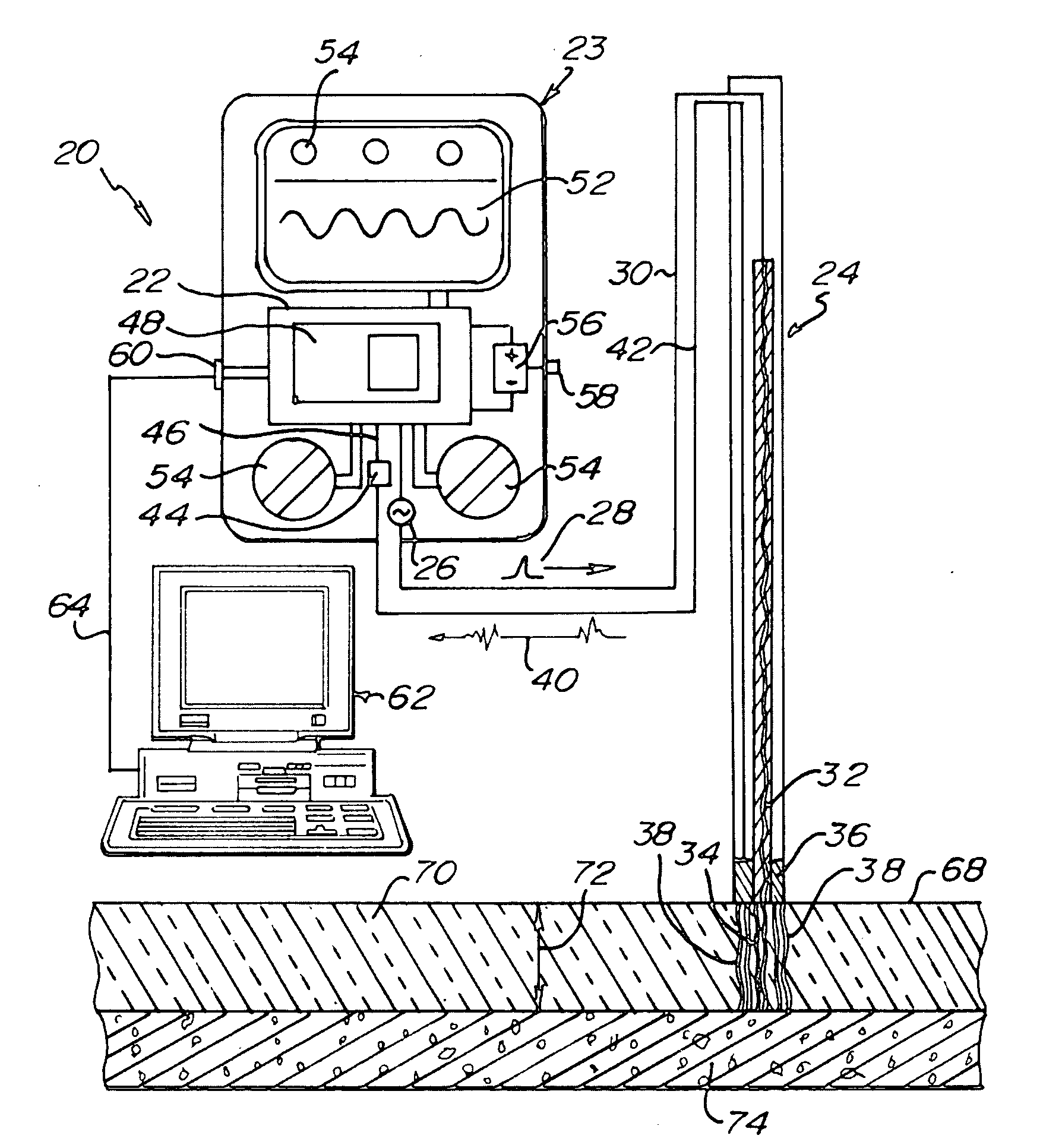
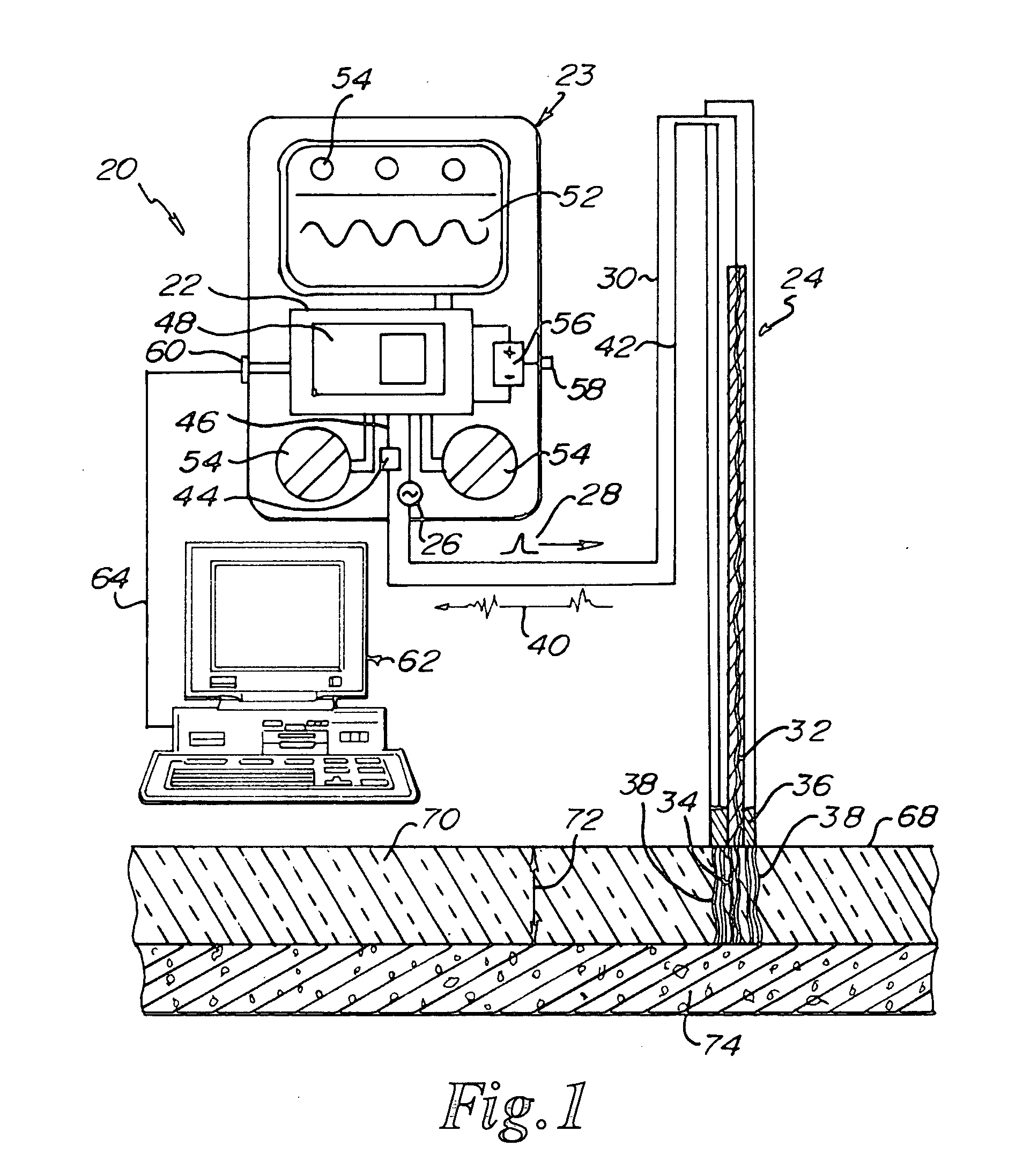
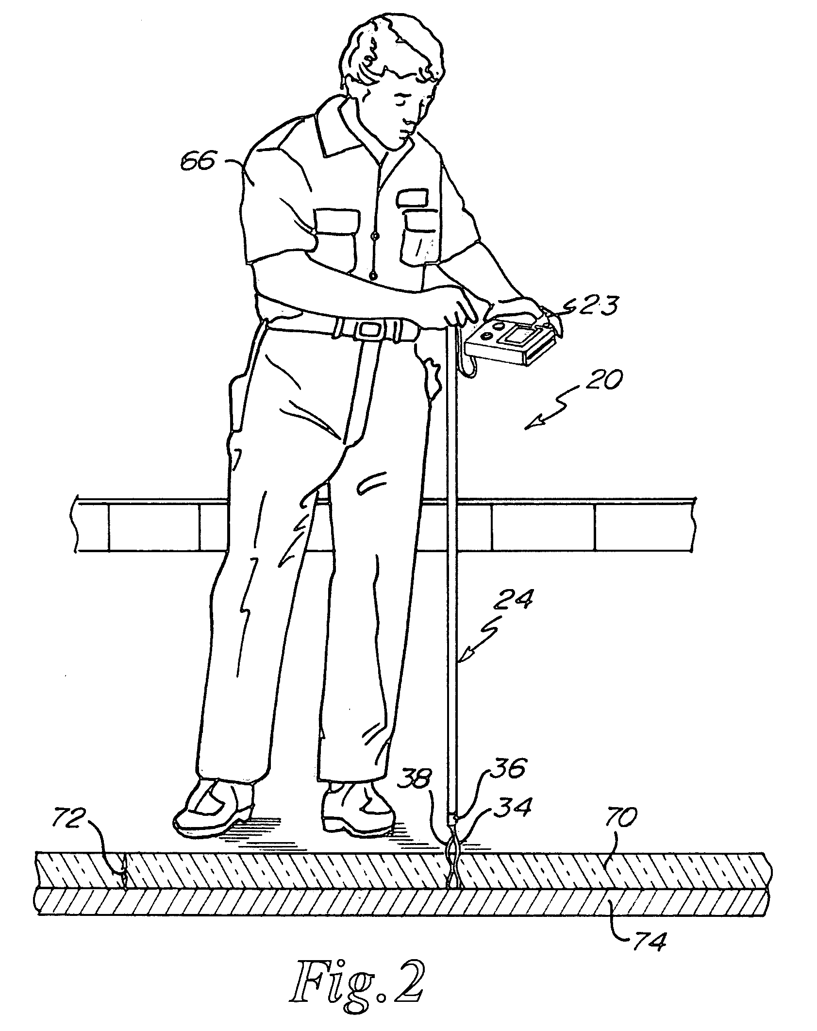
[0047]Referring to FIGS. 1 and 2, an ice thickness measurement system 20 is depicted in an embodiment of the invention comprising a signal processor 22 contained within a hand held console 23 and operatively coupled with a probe 24. The system depicted in FIGS. 1 and 2 is a dual element system comprising a transmitter or transmitting element 32 and a receiver or receiving element 36. The signal processor 22 may include a transmit signal or transmit pulse generator 26 that outputs a transmit signal or pulse 28 along a transmit lead 30 to the transmitter 32. The transmitter 32 converts the transmit signal 28 to a transmitted acoustic signal 34 that is congruent with or otherwise controlled by the frequency and amplitude of the transmit signal 28.

[0048]In one embodiment, the receiver 36 is configured to receive at least a portion of a reflected acoustical signal 38. The receiver 36 can be configured to convert the acoustic energy of the acoustical signal 38 to a received signal 40 that...


PUM

PropertyMeasurementUnit
thicknessaaaaaaaaaa
thickness measurementaaaaaaaaaa
timeaaaaaaaaaa

Abstract

An ice thickness measurement system for determining thicknesses of an ice sheet such as an ice rink that is positioned on a solid or granular substrate. The system determines the thickness of the ice sheet using an acoustic technique, is portable, and may include a display graphic or graphical user interface on the portable unit to direct operators of the unit where to conduct an array of measurements on the ice sheet. The system may also be compatible with a computer for downloading of data and uploading of graphical displays.

Description

RELATED APPLICATIONS[0001]This application claims the benefit of U.S. Provisional Application No. 60 / 918,829 filed Mar. 19, 2007, and which is hereby incorporated by reference in its entirety.COMPACT DISK[0002]A compact disc containing codes and information describing a preferred embodiment of the present invention is submitted herewith and is hereby incorporated by reference. The compact disc contains the following files and / or programs:TitleSize in BytesDate of Creationfonts.c266,040Mar. 14, 2008fonts.h2,367Mar. 14, 2008global.h164Mar. 14, 2008Ice Gauge.c57,262Mar. 14, 2008Ice Gauge.h11,629Mar. 14, 2008Ice Gauge.PJT1,202Mar. 14, 2008lcd128x64.c25,398Mar. 14, 2008lcd128x64.h5,884Mar. 14, 20088 files; 369,946 bytesTotal: 8 files; 369,946 bytesTECHNICAL FIELD[0003]The present disclosure relates generally to the measurement of thickness. More particularly, the disclosure relates to the non destructive measurement of an ice sheet situated on a solid or granular substrate.BACKGROUND OF ...

Claims


Application Information

Patent Timeline
Patent Type & Authority Applications(United States)
IPC IPC(8): G01N9/24
CPCG01B17/025
Inventor CLASEN, MARKMCGILL, ORRIN MILOERICKSON, PHILIP ERICTELL, ERNEST L.
Owner PRECICE TECH
Why Eureka
Try Eureka