Capacitor

Inactive Publication Date: 2008-12-04
SANYO ELECTRIC CO LTD
View PDF1 Cites 85 Cited by
  • Summary
  • Abstract
  • Description
  • Claims
  • Application Information

AI Technical Summary

Benefits of technology

[0023]The capacitor of the present invention can obtain the high charge capacity upon the high rate charging/discharging. Accordingly, it can be used as a capacitor charged/discharged with,

Problems solved by technology

However, there exists a problem that if charging/discharging is performed at a high rate with the carbon m

Method used


Image

  • Capacitor
  • Capacitor
  • Capacitor

Examples


examples 4 to 6

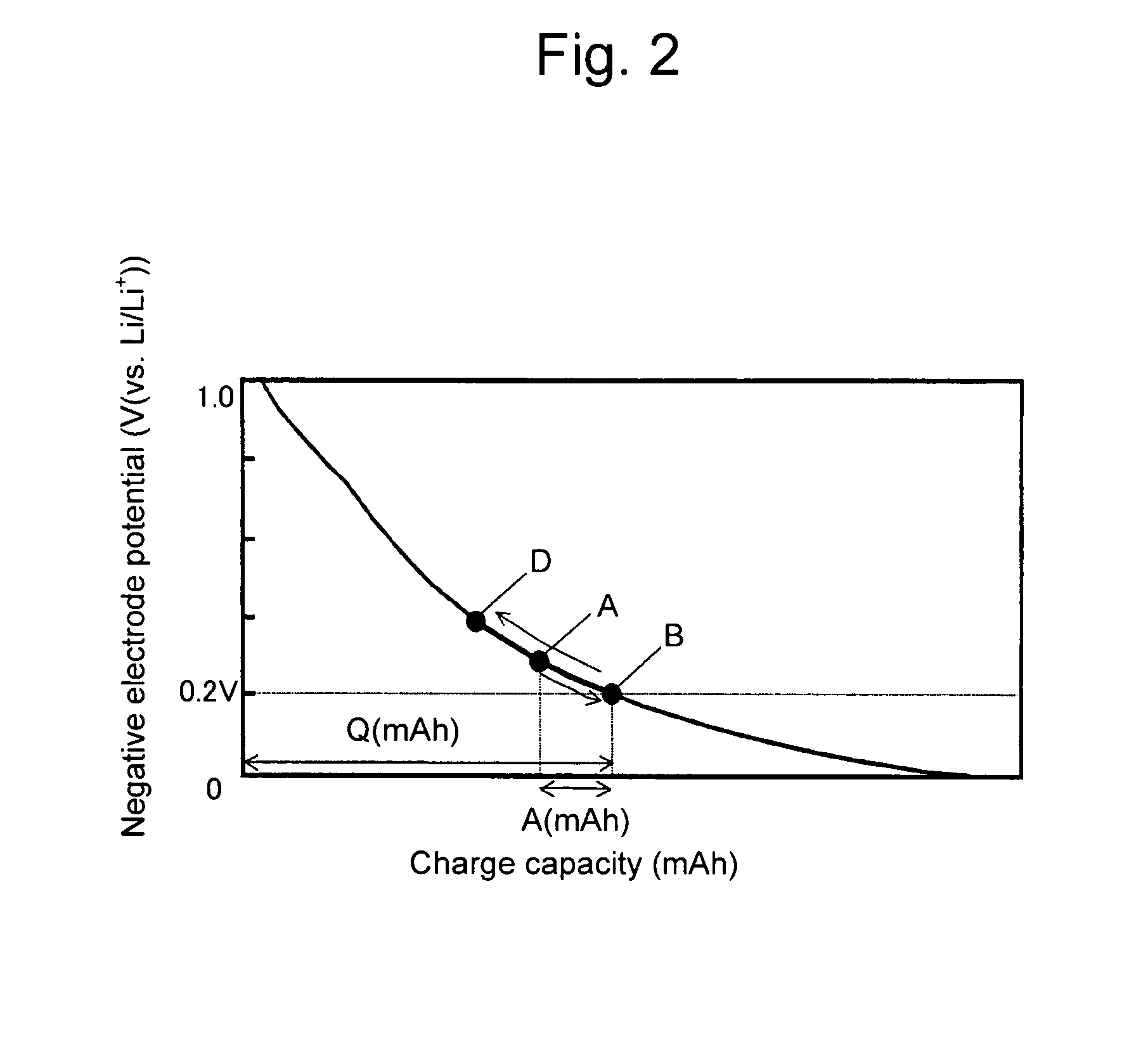
[0056]In Example 2 described above, the capacity at the time when lithium was extracted until the negative electrode potential was changed from 0.20 V (vs. Li / Li+) to 1.5 V (vs. Li / Li+) was 2.20 mAh. This is equivalent to the above-described negative electrode capacity Q. In Example 2, a ratio A / Q of the positive electrode capacity A to the negative electrode capacity Q was 0.19.

[0057]By increasing the thickness of the positive electrode, the capacity ratio A / Q was adjusted to 0.36 (Example 4), 0.50 (Example 5), or 0.55 (Example 6).

[0058][Preparation of Electrolyte]

[0059]The electrolyte was prepared by dissolving lithium hexafluorophosphate (LiPF6) in a mixed solvent of ethylene carbonate and diethyl carbonate having a volume ratio of 3:7 so as to achieve a LiPF6 concentration of 1 mol / liter.

[0060][Fabrication of Capacitor]

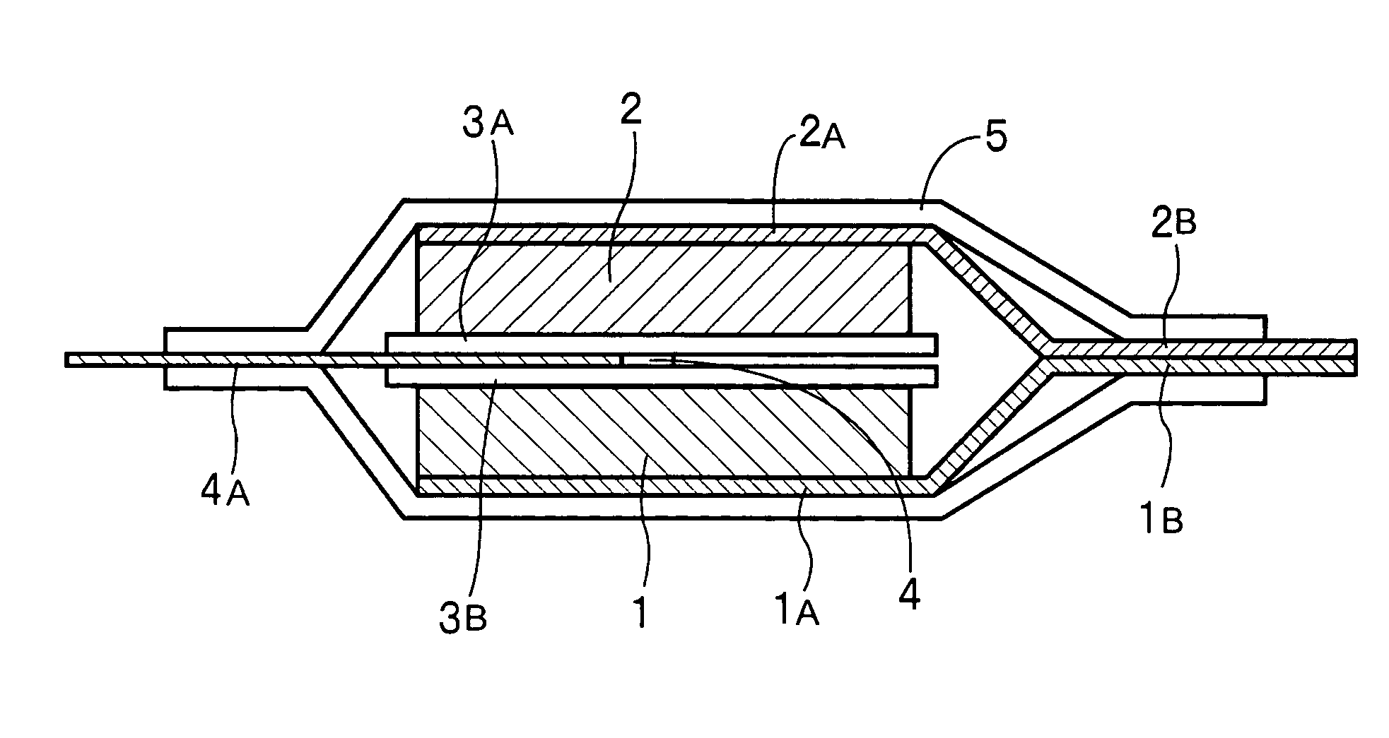
[0061]A polyolefin-based separator was inserted between the above-described positive and negative electrodes, which was then impregnated with the electrolyte and ...


PUM

PropertyMeasurementUnit
Timeaaaaaaaaaa
Electric chargeaaaaaaaaaa

Abstract

The present invention is characterized by obtaining a high charge/discharge capacity upon high rate charging/discharging in a hybrid capacitor having characteristics of both an electric double layer capacitor and a lithium-ion secondary battery. Specifically, the present invention is a capacitor comprising: a positive electrode 1 composed of a polarizable electrode containing activated carbon; a negative electrode 2 containing as an anode active material a carbon material capable of inserting/extracting lithium ion; and a nonaqueous electrolyte containing lithium ion, wherein a charge cutoff potential for the negative electrode 2 is within the range of 0.15 to 0.25 V (vs. Li/Li+).

Description

TECHNICAL FIELD[0001]The present invention relates to a hybrid capacitor having characteristics of both an electric double layer capacitor and a lithium-ion secondary battery.BACKGROUND OF THE INVENTION[0002]In recent years, a hybrid capacitor comprising a positive electrode composed of a polarizable electrode using activated carbon, a negative electrode using a material in which a carbon material capable of inserting or extracting lithium ion is made to insert lithium ion as an anode active material and an organic electrolyte using a lithium salt as a solute has attracted attention. This is described in, for example, Unexamined Japanese Patent Application Publications No. H08-107048, H11-54383, or 2005-101409.[0003]The hybrid capacitor is characterized by having performance combining characteristics of both a lithium-ion secondary battery and an electric double layer capacitor, and a higher energy density as compared with that of the electric double layer capacitor while having a h...

Claims


Application Information

Patent Timeline
IPC IPC(8): H01G9/032H01G11/06H01G11/22H01G11/30H01G11/32H01G11/38H01G11/42H01G11/50H01G11/70H01G11/78H01G11/86
CPCH01G9/038H01G9/058Y10T29/417H01G11/06Y02E60/13H01G9/155H01G11/50H01G11/32H01G11/14H01G11/22
Inventor ENDO, KOJINAKAHARA, YASUONONOUE, HIROSHI
Owner SANYO ELECTRIC CO LTD
Why Eureka
Try Eureka