Topographical Templating of Polymeric Materials Using Cellular Morphology

a polymeric material and morphology technology, applied in the field of topographical templating of polymeric materials and substrates, can solve problems such as not being the ideal design for such structures, and achieve the effects of increasing cellular adhesion and integration, and promoting cell adhesion

Inactive Publication Date: 2008-12-04
BROWN UNIVERSITY
View PDF5 Cites 18 Cited by
  • Summary
  • Abstract
  • Description
  • Claims
  • Application Information

AI Technical Summary

Benefits of technology

[0014]The invention is based on the premise that employing substrates having cell-templated surface features that impart the surface geometry, i.e., the morphology, of the cell to the substrate results in increased cellular adhesion and integration into the cellular environment when the substrate is employed as an implant to induce or stimulate cell and tissue growth, differentiation and regeneration. Thus, the cells are employed as templates to impart the morphology of the cell to the substrate. The substrate, now incorporating the external morphology of the cell template, can then be employed to control the growth and differentiation of cells in vitro or in vivo. Prior work in the field, some of which is discussed above, suggests that substrates with nanometer-scale and micrometer-scale surface features can promote cell adhesion in contrast to substrates with smooth surfaces. The prior work has focused on producing substrates having arbitrarily designed three-dimensional surface features composed, for example, of regularly-spaced ridges and troughs. However, neurite bridging across the troughs of such substrates has been observed, suggesting that regularly-spaced ridges and troughs may not be the ideal design for such structure. See Goldner, et al., supra. To our knowledge, the use of cells to create the three-dimensional surface features or morphologies in substrates, including in implantable substrates, has not heretofore been suggested or disclosed.

Problems solved by technology

However, neurite bridging across the troughs of such substrates has been observed, suggesting that regularly-spaced ridges and troughs may not be the ideal design for such structure.

Method used


Image

  • Topographical Templating of Polymeric Materials Using Cellular Morphology
  • Topographical Templating of Polymeric Materials Using Cellular Morphology
  • Topographical Templating of Polymeric Materials Using Cellular Morphology

Examples


example 1

Preparation of Cell-Templated Substrates

[0066](i) Template Cell Culture Alignment

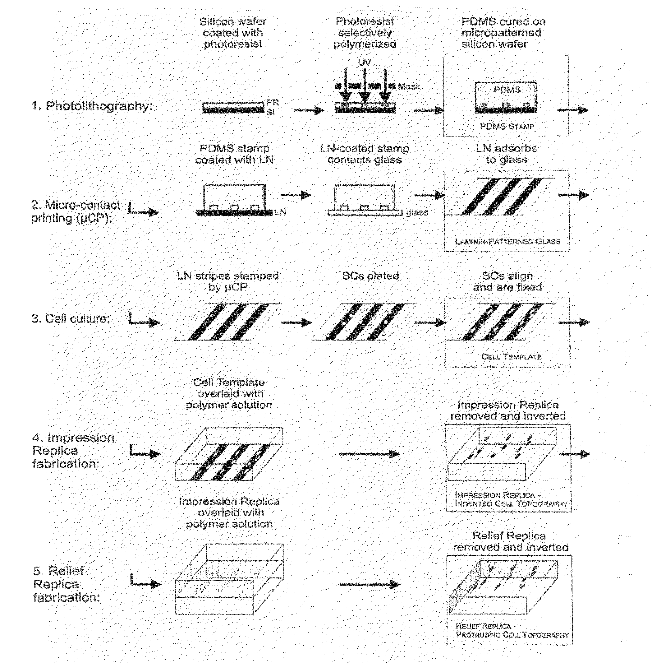
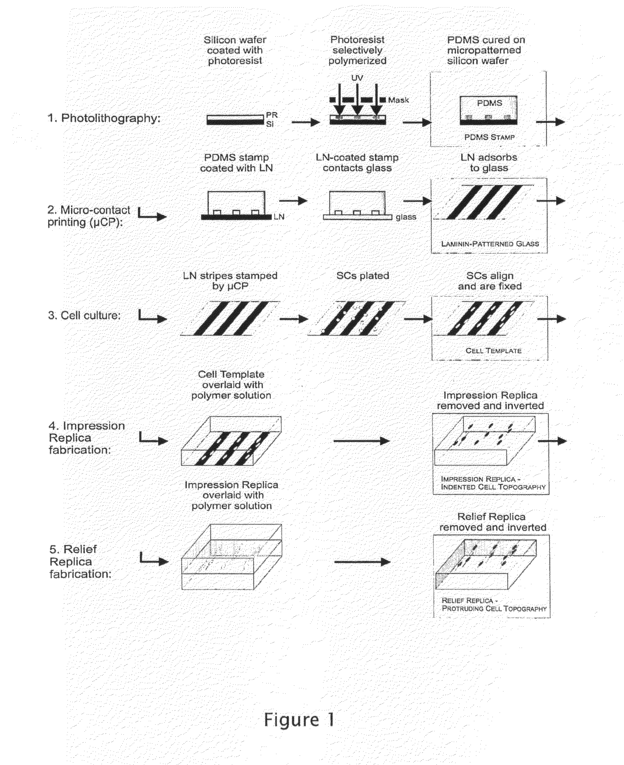
[0067]Aligned cell cultures, for example Schwann cell cultures, are prepared by micro-stamping laminin in a striped pattern onto a glass coverslip, then culturing Schwann cells on the micropatterned coverslip. For micro-stamping, a grooved PDMS stamp is prepared as described in Goldner et al. (2005). Briefly, the pattern is designed in AutoCAD LT 2004 (Autodesk Corp.) and printed at 10,000 dpi onto a mylar mask. Standard photolithographic techniques are used to transfer the pattern onto Si wafers (Silicon Sense, Inc.) spin-coated with a 50 μm layer of negative tone Nano SU-8 50 photoresist (Microtech Corp.), resulting in repetitive grooves with 60 μm groove, width, 60 μm plateau width, and 50 μm groove depth. Finished features are silaned to prevent adhesion during subsequent casting.

[0068](ii) Polymer Stamp Manufacture

[0069]Sylgard 184 PDMS Elastomer base is mixed with Sylgard 184 PDSM curing agent at ...

example 2

Fabrication of Patterned Molds from Cellular Template

[0075](i) Fabrication of PDSM Molds

[0076]PDMS is prepared using Sylgard®184 from Dow Corning. Elastomer is combined with curing agent at a ratio of 10:1 elastomer base:curing agent and mixed.

[0077]De-gassed PDMS is poured onto the fixed Schwann cells to form a layer 1-3 mm, de-gassed again for approximately 20 minutes, and cured on a hotplate at 95° C. for 1 hour. After removing from the hotplate, PDMS is peeled off. This film substrate (PDMS1) contains indented regions that replicate the inverse of the cell morphology. To generate a film substrate that contains protruding regions that replicate the cell morphology (PDMS2), fresh PDMS is prepared, poured onto the PDMS1, and removed as described above. Of note, PDSM1 remains intact following its use as a template and it can be re-used either as a template for additional PDSM2 samples or for future experiments.

[0078](ii) Fabrication of PU molds

[0079]Polyurethane (PU) is prepared usi...

example 3

In Vitro Stimulation of Nerve Growth

[0080]Cell cultures are incubated at 37° C. and 5% CO2 in a humidified environment. For culture on the cell templated substrates, cells are initially plated at specified densities onto the substrates in 100 μl of appropriate plating medium. After cells adhere to substrates for 3 h, 3 ml of appropriate base culture media are added as described in Example 1. DRG are grown in “neuronal media”, which is base media supplemented with 50 ng / ml Nerve Growth Factor (NGF).

[0081]The analysis of guided and stimulated cell growth employing the PDMS patterned molds from the cellular templates can be carried out using the same techniques, materials and methods described in detail in Goldner, et al, Biomaterials 27 (2006) 460-472.

[0082](i) Motion Tracking Analysis of DRG Cells

[0083]Two aligned SC PDMS1 and two aligned SC PDSM2 cell templated films are coated with PLL / LN for 1 h using standard methods. A flat film of PDMS was used as a control and likewise coated....


PUM

PropertyMeasurementUnit
thickaaaaaaaaaa
thickaaaaaaaaaa
widthaaaaaaaaaa

Abstract

Substrates for influencing the organization, spreading or adhesion of a selected cell to induce or stimulate growth, differentiation or regeneration of the cell or of tissue constituting the cells are provided as well as methods of making such substrates and methods of using such substrates.

Description

FIELD OF THE INVENTION[0001]The invention relates to materials and methods for the topographical templating of polymeric materials and substrates that can be employed to induce and stimulate guided cell growth.BACKGROUND OF THE INVENTION[0002]Polymers, natural and synthetic, have been employed in drug delivery and in biomedical engineering for many years. In biomedical engineering, the list of such usable polymers is extensive. So is the list of shapes, sizes and patterns proposed by researchers in cell and tissue engineering. The desire has been to create surfaces and forms that influence cell adhesion, spreading, growth and organization in a manner which induces and stimulates controlled and selective growth and differentiation, or regeneration, of cells and tissues.[0003]For example, in the field of nerve regeneration, it has been proposed to employ substrates having surface containing grooves in the interior surface of guidance conduits, with chemical, cellular or electrical “cu...

Claims


Application Information

Patent Timeline
Patent Type & Authority Applications(United States)
IPC IPC(8): A61F2/04C12N5/06A61K38/16A61K38/18A61P25/00B05D3/02A61F2/28C12N5/079
CPCA61L27/18A61L27/507A61L27/54A61L27/58A61L2300/414A61L2300/604C12N5/0068C12N5/0622C12N2533/52C12N2535/10C08L67/04A61K38/185A61K38/39A61P25/00C12N5/0075C12N5/0619C12N2531/00C12N2533/30C12N2535/00C12N2537/00
Inventor HOFFMAN-KIM, DIANEBRUDER, JAN M.
Owner BROWN UNIVERSITY
Why Eureka
Try Eureka