Evaporative cooling system

a cooling system and evaporative technology, applied in the field of cooling systems, can solve the problems of affecting the efficiency of evaporation, and the inability to increase the mounting density of heating elements, so as to improve cooling efficiency, efficiently perform evaporative cooling, and increase latent heat flux

Inactive Publication Date: 2008-12-11
HITACHI LTD
View PDF5 Cites 27 Cited by
  • Summary
  • Abstract
  • Description
  • Claims
  • Application Information

AI Technical Summary

Benefits of technology

[0032]Further, another feature is that the planar heating element is substantially vertically arranged, and that the refrigerant liquid is supplied to the upper part of the vaporizing plate, and the air containing the refrigerant vapor and the residual refrigerant liquid are discharged from the lower part of the vaporizing plate. Thereby, it is possible to configure the liquid supply system or the discharge system which is suitable for the vertical heating element, and in which the cooling system can be miniaturized.
[0033]Further, another feature is that the closed circuit system is configured by the liquid supply system for supplying the refrigerant to the vaporizing plate, the exhaust system, and the reflux system which returns the refrigerant to the liquid supply system, and that the open circuit system is configured by the air supply system for intaking air from ambient air, the exhaust system, and the reflux system for discharging the air to ambient air. Thereby, it is possible to increase the latent heat flux La by supplying air of a low vapor pressure ea to the vaporizing plate by the use of ambient air in the simple open loop system, while circulating the refrigerant in the closed circuit system.
[0034]Further, another feature is that the system for effecting reflux from exhaust system through the primary heat exchange system is miniaturized in such a way that the primary refrigerant vapor with heat taken from the heating element in the primary heat exchange system is cooled and condensed by the secondary refrigerant, and that the heat absorbed by the secondary refrigerant from the primary refrigerant vapor is discharged in the secondary heat exchange system, and is that the cooling efficiency is improved by keeping the heat exhaust place in the secondary heat exchange system away from the vicinity of the heating element.
[0035]Further, another feature is that the evaporative cooling is efficiently performed in such a way that a required amount of the refrigerant and air is supplied to the vaporizing plate by controlling the supply liquid amount, the supply liquid temperature, the supply air amount or the supply air temperature according to the heat generation amount, the power consumption, the operation rate, or the temperature of the heating element.
[0036]According to claims 1-5 of the present application, it is possible to efficiently perform the evaporative cooling even for a heating element with high heat generation density by increasing the latent heat flux La. According to claims 6-13 of the present application, it is possible to effect the reduction in size and weight of the cooling system configured by the liquid supply system, the air supply system, the exhaust system, the reflux system, and the like. The present invention is particularly effective to increase the mounting density and to improve performance of major devices, such as a processor and an LSI in information platform devices, such as a server, a network, and a storage.

Problems solved by technology

Thus, there is a problem that vapor pressure of the refrigerant in the vicinity of the heating element is increased to make it difficult to evaporate.
Thus, there is also a problem that the mounting density of the heating element cannot be increased.
Thus, there is a problem that these components hinder the miniaturization and the improvement of reliability of the cooling system.
Thus, there is a problem that the vapor pressure of the refrigerant is increased in the circulatory system and thereby the vaporization efficiency is lowered.
However, such configuration prevents the miniaturization and weight reduction of the cooling system.
Thus, there is a problem that as the evaporation is performed on the front side, the vapor pressure is increased on the back side to thereby make it difficult to evaporate the refrigerant.
As described above, the conventional techniques have problems that the evaporative cooling efficiency is low and the miniaturization and weight reduction of the cooling system is difficult.

Method used


Image

  • Evaporative cooling system
  • Evaporative cooling system
  • Evaporative cooling system

Examples


first embodiment

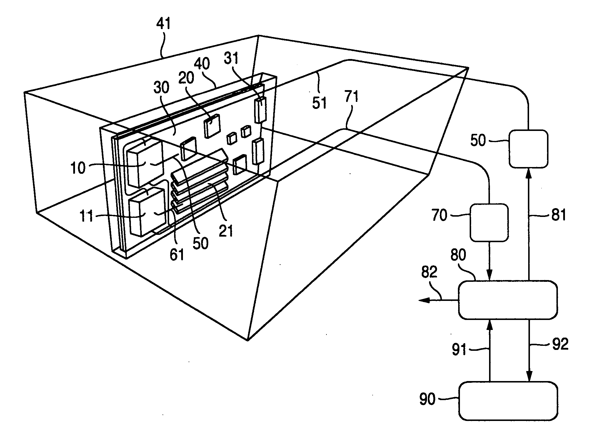
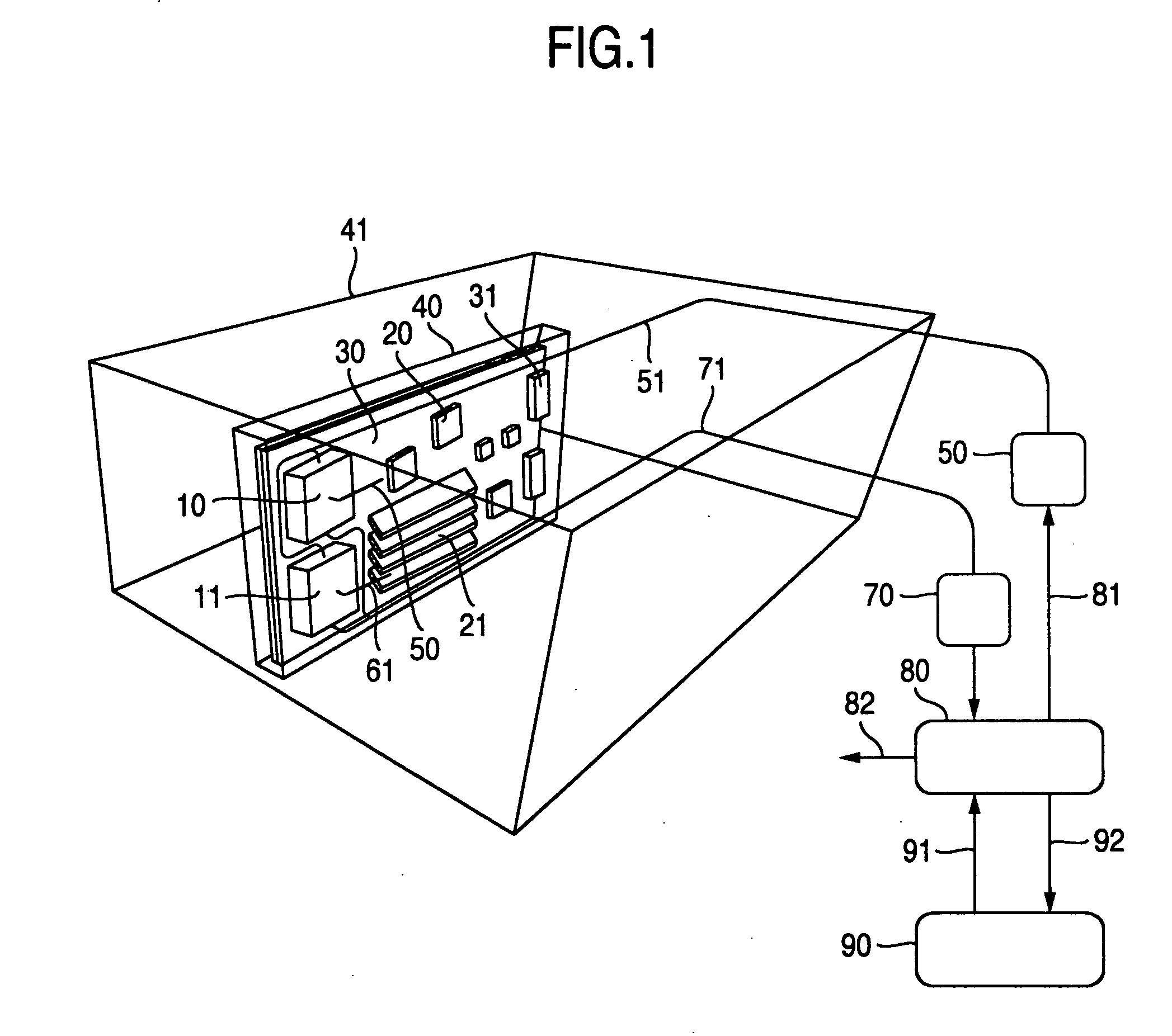
[0052]FIG. 1 is a view showing a configuration of an evaporative cooling system of a first embodiment according to the present invention, and an example in which the present invention is applied to a blade server system. The blade server system comprises a plurality of blade servers 40, a back plane connected to the plurality of blade servers 40, an I / O module, a switch module, a storage module, a management module, a power supply module, an air cooling fan module, and the like, and a server chassis 41 for housing these components. The blade server 40 comprises a processor to which evaporative cooling modules 10 and 11 are attached, a chip set 20, a memory module 21, a mother board 30, a connector 31 for effecting connection with the back plane, and the like, and a case for covering these components.

[0053]The evaporative cooling system comprises the evaporative cooling modules 10 and 11 in contact with the processor which is a heating element, a liquid supply system which includes a...

second embodiment

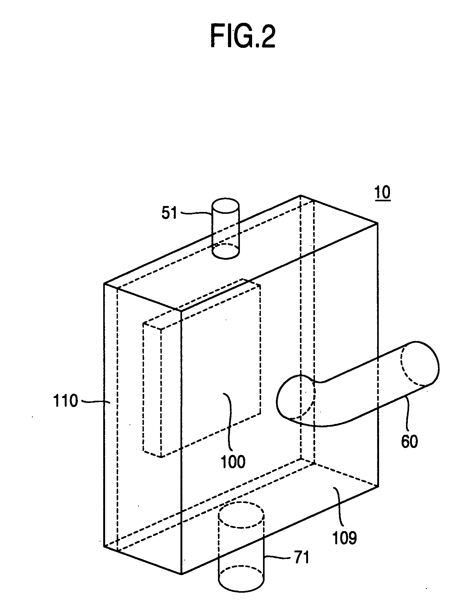
[0065]In the second embodiment, the evaporative cooling modules 10 and 11 are attached to the processor, the refrigerant liquid is evaporated from the vaporizing plate having an area larger than that of the processor chip and having capillaries on the surface thereof. The refrigerant liquid is supplied from an upper part of the evaporative cooling modules 10 and 11 via the liquid supply tube 51. The warm air is supplied to the modules 10 and 11 via the air supply tubes 60 and 61 from the direction different from the direction in which the refrigerant liquid is supplied. The refrigerant vapor and the residual liquid are discharged from a lower part of the modules 10 and 11. The condensed refrigerant liquid collected by the primary heat exchanger 80 is again returned to the modules 10 and 11 through the liquid supply pump 50. The refrigerant is circulated in the closed circuit circulatory system, while the air is passed through in the open circuit system from the warm air blower 62 to...

sixth embodiment

[0075] the liquid supply pump can be eliminated from the liquid supply system by using the exhaust pressure of the exhaust pump and the weight of the refrigerant liquid itself. Thus, it is possible to reduce the power required for the cooling system, and also possible to reduce the size of the blade server system.

[0076]The evaporative cooling system according to the present invention is suitable for information platform devices, such as a server, a network, and a storage which are required to have higher performance and higher density. The evaporative cooling system according to the present invention can be widely applied to cool an apparatus having a heating element, such as, for example, electronic devices such as a PC and a portable telephone, power devices such as a generator and a fuel cell, and dynamic devices such as a motor vehicle and a railroad vehicle.


PUM


Abstract

The evaporative cooling system comprises: evaporative cooling modules, a liquid supply system which comprises a liquid supply pump and a tube, and which supplies a refrigerant liquid to the evaporative cooling modules; an air supply system which comprises air supply tubes, and which supplies warm air to the evaporative cooling modules; an exhaust system which comprises an exhaust pump and a tube, and which exhausts air containing a refrigerant vapor from the evaporative cooling modules; a reflux system which comprises a primary heat exchanger and a reflux tube, and which condenses the refrigerant vapor to return the condensed refrigerant liquid to the liquid supply system; and a heat exhaust system which comprises a secondary heat exchanger and tubes, and which discharges heat absorbed from the primary heat exchanger.

Description

INCORPORATION BY REFERENCE[0001]The present application claims priority from Japanese application JP 2007-149882 filed on Jun. 6, 2007, the content of which is hereby incorporated by reference into this application.BACKGROUND OF THE INVENTION[0002]The present invention relates to a cooling system for a heating element, and more particularly to an evaporative cooling system suitable for information platform apparatuses such as a server, a network, and a storage which are required to have higher performance and higher density.[0003]Conventionally, evaporative cooling is known as means for efficiently cooling heating elements, such as a processor, an LSI, electronic devices, power devices, and dynamic devices. The evaporative cooling utilizing latent heat of refrigerant is considered promising for improving the cooling efficiency and reducing the weight and size of cooling system, as compared with air cooling and liquid cooling which utilize heat conduction and heat transfer from a hea...

Claims


Application Information

Patent Timeline
Patent Type & Authority Applications(United States)
IPC IPC(8): F25B29/00F28D15/00F28D15/04F28F13/06
CPCB60K2001/003F25B23/006F25B25/005F28D15/0266H01L23/427H01L2924/0002H05K7/20809H01L2924/00
Inventor KATO, TAKESHIKONDO, YOSHIHIROSAITO, TATSUYAHAMANAKA, NAOKI
Owner HITACHI LTD
Why Eureka
Try Eureka