Structural system for optimizing performance of a millimeter wave concealed object detection system

a technology of hidden object detection and structural system, which is applied in the direction of individual entry/exit registers, instruments, and using reradiation, etc., can solve the problems of exposing not only security personnel to danger, but also other individuals in the vicinity, and reducing the risk to the parent structure. , the effect of optimizing performan

Inactive Publication Date: 2008-12-11
MICROSEMI
View PDF1 Cites 25 Cited by
  • Summary
  • Abstract
  • Description
  • Claims
  • Application Information

AI Technical Summary

Benefits of technology

[0022]Another particular advantage provided by embodiments of the structural system for optimizing performance of a millimeter wave concealed object detection system is the ability to provide stand-alone or add-on implementations.
[0023]Another particular advantage provided by embodiments of the structural system for optimizing performance of a millimeter wave concealed object detection system is the ability to operate as either an entry portal for concealed weapons or object detection system or as an exit portal for theft prevention or both.
[0024]Another particular advantage provided by embodiments of the structural system for optimizing performance of a millimeter wave concealed object detection system is that the need to adapt the concealed object detection system camera(s) to an uncontrolled environment is eliminated.
[0025]Another particular advantage provided by embodiments of the structural system for optimizing performance of a millimeter wave concealed object d

Problems solved by technology

The concealed objects that present a danger are weapons, explosives, contraband and other similar items that may endanger security personnel and other individuals in the proximity.
An inherent deficiency of this type of security system is the fact that it exposes not only the security personnel to danger, but also oth

Method used


Image

  • Structural system for optimizing performance of a millimeter wave concealed object detection system
  • Structural system for optimizing performance of a millimeter wave concealed object detection system
  • Structural system for optimizing performance of a millimeter wave concealed object detection system

Examples


first embodiment

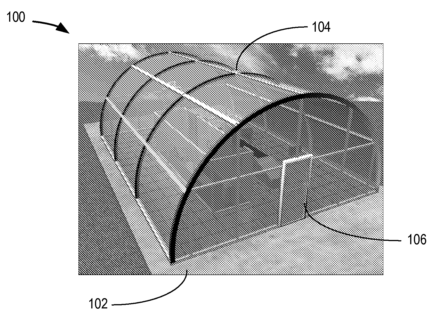
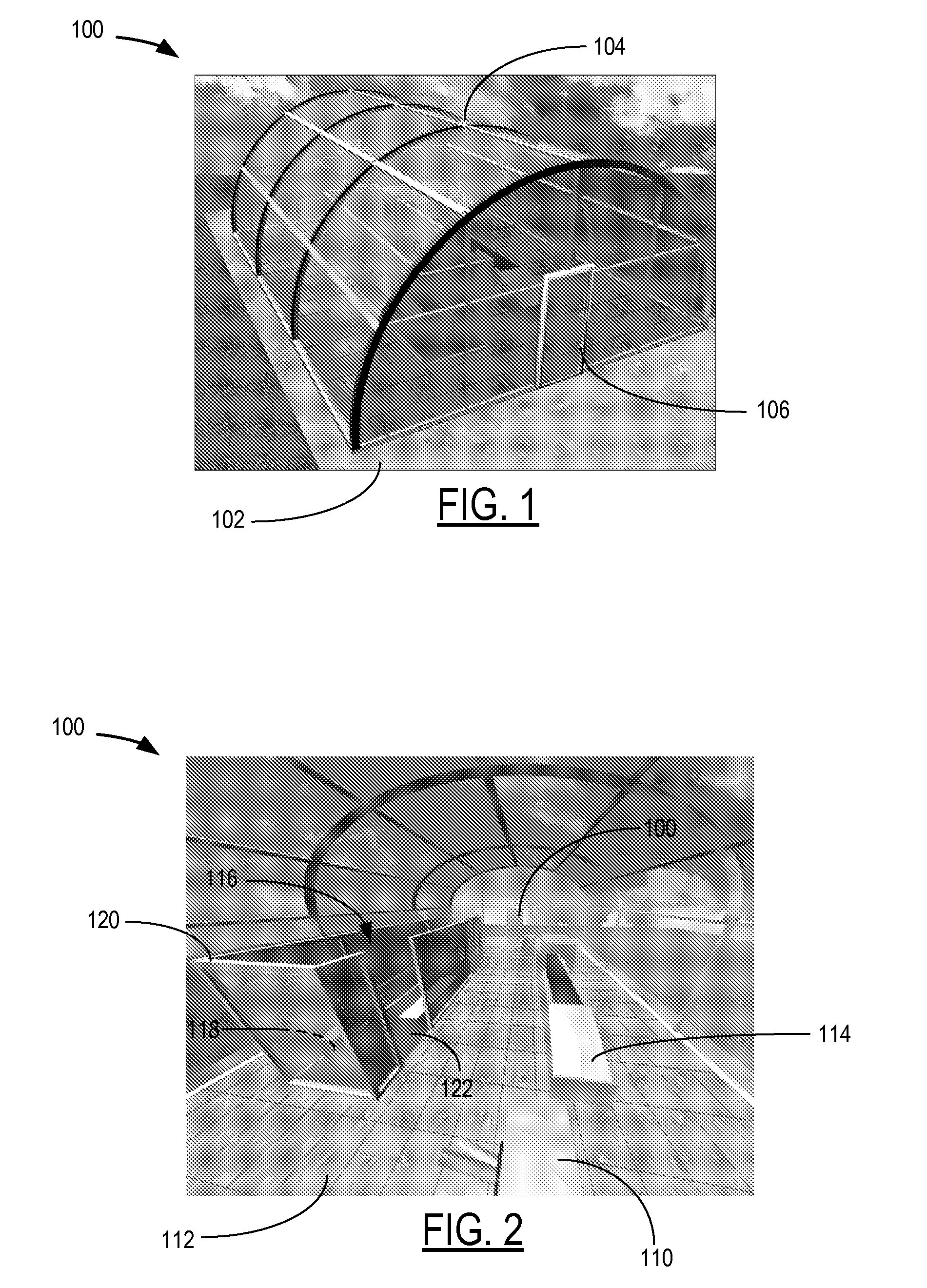
[0058]Referring to FIG. 1, a particular illustrative first embodiment of a structural system for optimizing performance of a millimeter wave concealed object detection system is disclosed. The structural system takes the form of a separate free-standing structure containing a controlled entry point, a concealed object detection system, and a controlled exit point that is directly attached to (or in close proximity to) an entry or exit point to the parent structure. The parent structure may be an airport terminal or office building, for example. The structural system includes a foundation 102, external shell 104, an entry barrier 106 located at one end of the structure 100, and an exit barrier 108 located at the opposite end of the structure 100. The entry barrier 106 and exit barrier 108 control entry and exit from the structure 100 and may be equipped with magnetic or other automatic locking devices, doors, gate, turnstiles or the like, or may be manually opened. Permission to ente...

second embodiment

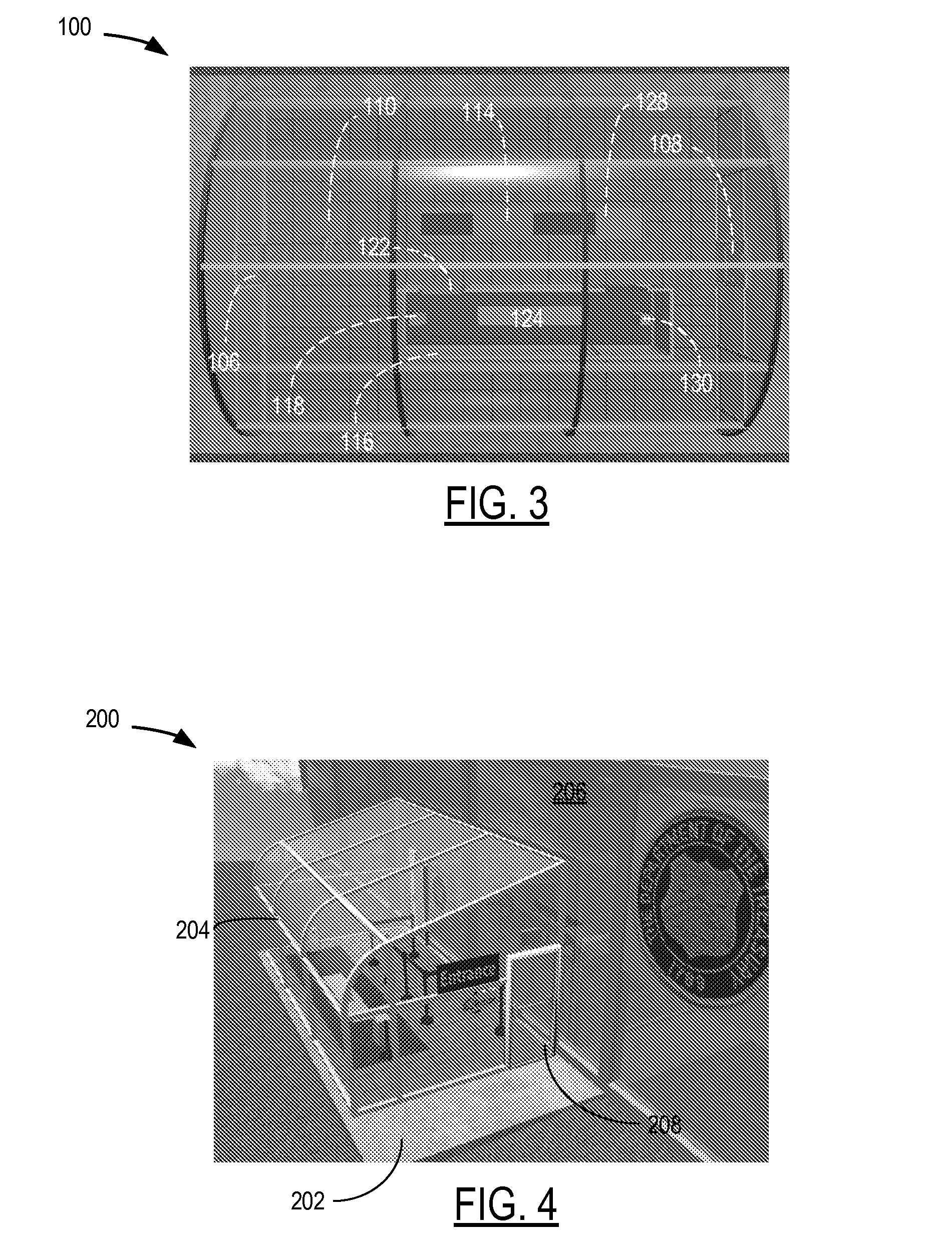
[0064]Referring now to FIG. 4, a particular illustrative second embodiment of the structural system for optimizing performance of a millimeter wave concealed object detection system is disclosed. The structural system is based on a vestibule 200 or similar structure constructed directly adjacent to a new or existing parent structure such as an office building or similar facility. The structural system includes separate entry and exit points, and containing a concealed object or weapons detection system, that can be positioned in series with the legacy entry or exit of a parent structure such that instead of directly entering or exiting the parent structure via the legacy entrance / exit, entrance must be effected by first traversing the detection system and / or exit must be effected by subsequently traversing the detection system. Vestibule 200 includes a foundation 202, external walls 204, a wall or similar structure 206 shared with the adjacent building, an entry barrier 208 located ...

fourth embodiment

[0069]Referring now to FIG. 11, a particular illustrative fourth embodiment of a structural system for optimizing performance of a millimeter wave concealed object detection system is disclosed. The disclosed structural system is based on four-unit arrangement designed for high security detection of concealed weapons, explosives, and other objects. The structural system 400 is designed for use within a building, shed, or other structure and includes a concealed object or weapons detection system, that can be positioned in series with the entry or exit of the parent structure, shed or structure or elsewhere as appropriate. The structural system 400 may be have a floor covering 402 or additional add-on flooring designed to optimize performance of the millimeter wave concealed object detection system 412 by eliminating or mitigating spurious millimeter wave emissions and / or reflections from outside or inside the parent structure, shed, or structure. In addition, the structural system 4...


PUM


Abstract

A structural system for optimizing the performance of a millimeter wave concealed object detection system is disclosed. In a particular embodiment, a shell is provided to house and protect the millimeter wave concealed object detection system so that the detection system can operate optimally in a controlled and managed environment by eliminating or mitigating spurious millimeter wave emissions or reflections from outside or inside the shell. The shell can be free-standing or attached to a parent structure. The entry and exit to the system is controlled by entry and exit barriers. In addition, an inspection lane is configured according to each particular application to guide a subject through the detection system.

Description

I. CROSS REFERENCE TO RELATED APPLICATIONS [0001]This application claims the benefit of U.S. Provisional Application No. 60 / 942,469, filed Jun. 7, 2007, and U.S. Provisional Application No. 60 / 942,467, filed Jun. 7, 2007. The disclosures of the provisional applications are incorporated herein by reference.II. FIELD [0002]The present disclosure relates in general to the field of concealed object detection, and in particular to a structural system for optimizing performance of a millimeter wave concealed object detection system.III. DESCRIPTION OF RELATED ART [0003]Security systems can be found at airports, train stations, arenas, construction sites, and other public, private, commercial and industrial facilities. In addition, security systems are used in field military operations to secure boundaries. One of the principal concerns of operators of security systems is the need to protect security personnel and innocent bystanders in the course of conducting a search of a person for con...

Claims


Application Information

Patent Timeline
IPC IPC(8): G01S13/00E04B1/32
CPCB64F1/368G01S7/00G01S13/887G07C9/00166G01V8/005G07C9/38
Inventor DALY, ROBERT PATRICKREINPOLDT, WILLEM H.STRONG, MICHAEL F.TARR, JONATHON Y.
Owner MICROSEMI
Why Eureka
Try Eureka