Radio Transmission Device and Radio Reception Device

Active Publication Date: 2008-12-11
SUN PATENT TRUST
View PDF16 Cites 49 Cited by
  • Summary
  • Abstract
  • Description
  • Claims
  • Application Information

AI Technical Summary

Benefits of technology

[0009]The present inventi

Problems solved by technology

In mobile communications, when this kind of broadband transmission is performed using a single carrier, BER (Bit Error R

Method used


Image

  • Radio Transmission Device and Radio Reception Device
  • Radio Transmission Device and Radio Reception Device
  • Radio Transmission Device and Radio Reception Device

Examples


Example

Embodiment 1

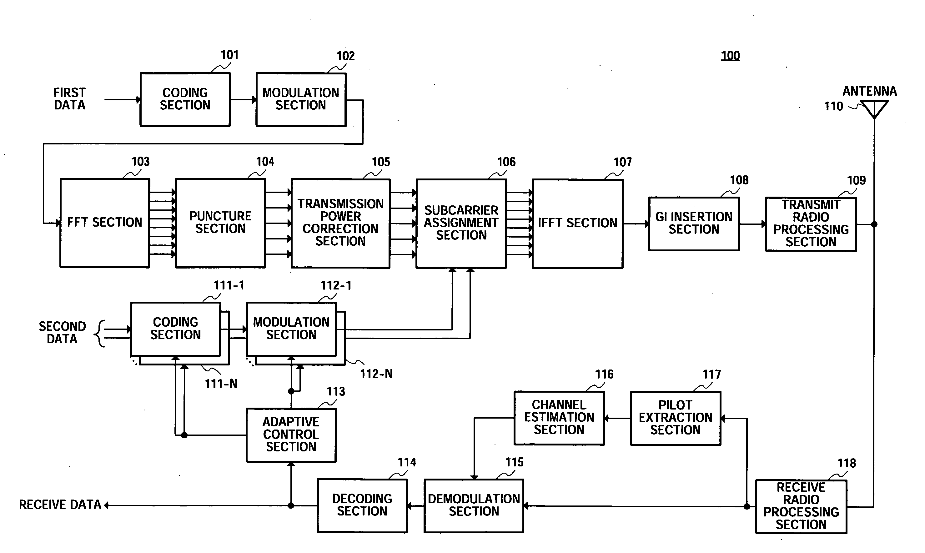
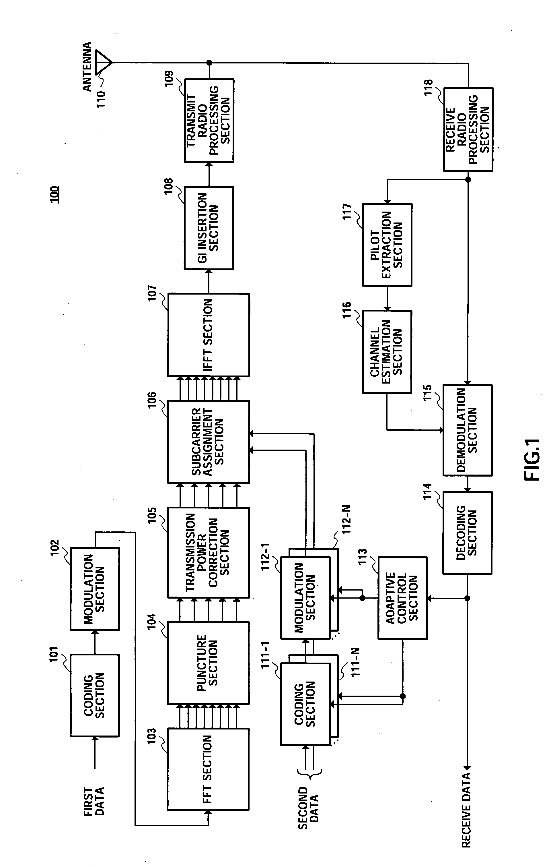
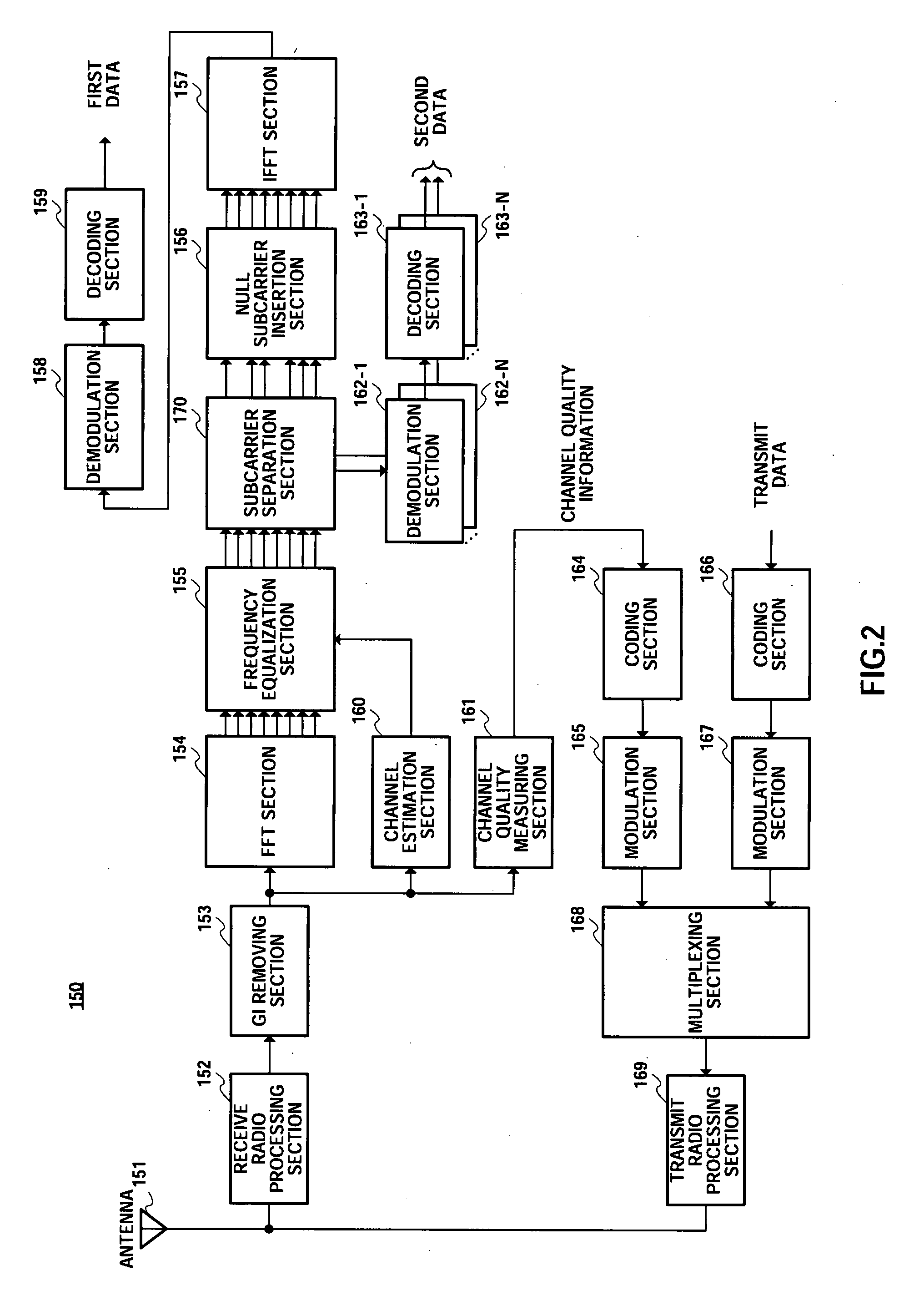
[0040]FIG. 1 is a block diagram showing the configuration of a radio transmitting apparatus according to Embodiment 1 of the present invention, and FIG. 2 is a block diagram showing the configuration of a radio receiving apparatus that performs radio communication with radio transmitting apparatus 100 in FIG. 1.

[0041]Radio transmitting apparatus 100 in FIG. 1 has coding section 101, modulation section 102, FFT (Fast Fourier Transform) section 103, puncture section 104, transmission power correction section 105, subcarrier assignment section 106, IFFT (Inverse Fast Fourier Transform) section 107, GI (Guard Interval) insertion section 108, transmit radio processing section 109, antenna 110, N (where N is an integer value of 2 or above) coding sections 111-1, . . . , 111-N, N modulation sections 112-1, . . . , 112-N, adaptive control section 113, decoding section 114, demodulation section 115, channel estimation section 116, pilot extraction section 117, and receive radio p...

Example

Embodiment 2

[0092]FIG. 6 is a block diagram showing the configuration of a radio transmitting apparatus according to Embodiment 2 of the present invention, and FIG. 7 is a block diagram showing the configuration of a radio receiving apparatus that performs radio communication with radio transmitting apparatus 200 in FIG. 6. Radio transmitting apparatus 200 in FIG. 6 and radio receiving apparatus 250 in FIG. 7 have similar basic configurations to those of radio transmitting apparatus 100 and radio receiving apparatus 150 described in Embodiment 1, and therefore identical configuration elements are assigned the same reference numerals, and detailed descriptions thereof are omitted.

[0093]Radio transmitting apparatus 200 has puncture section 201 and subcarrier assignment section 202 instead of puncture section 104 and subcarrier assignment section 106 described in Embodiment 1. Also, the configuration of radio transmitting apparatus 200 additionally includes control information processi...

Example

Embodiment 3

[0113]FIG. 10 is a block diagram showing the configuration of a radio transmitting apparatus according to Embodiment 3 of the present invention, and FIG. 11 is a block diagram showing the configuration of a radio receiving apparatus that performs radio communication with radio transmitting apparatus 300 in FIG. 10. Radio transmitting apparatus 300 in FIG. 10 and radio receiving apparatus 350 in FIG. 11 have similar basic configurations to those of radio transmitting apparatus 100 and radio receiving apparatus 150 described in Embodiment 1, and therefore identical configuration elements are assigned the same reference numerals, and detailed descriptions thereof are omitted.

[0114]The configuration of radio transmitting apparatus 300 does not include puncture section 104 and transmission power correction section 105 described in Embodiment 1, and has subcarrier assignment section 301 instead of subcarrier assignment section 106, and IFFT section 302 instead of IFFT section ...


PUM


Abstract

There is disclosed a radio transmission device capable of improving the throughput. The radio transmission device (100) transmits a first signal and a second signal which are different from each other. In the radio transmission device (100), an FFT unit (103) subjects first data to an FFT process. A sub-carrier allocation unit (106) maps the first data which has been subjected to the FFT process and the second data into different frequencies. An IFFT unit (107) subjects the mapped signal to the IFFT transform. A transmission radio processing unit (109) transmits the signal which has been subjected to the IFFT processing, with a single carrier.

Description

TECHNICAL FIELD[0001]The present invention relates to a radio transmitting apparatus and radio receiving apparatus and more particularly to a radio transmitting apparatus and radio receiving apparatus used in a mobile communication system in which single-carrier frequency equalization technology is applied.BACKGROUND ART[0002]In recent years, looking toward next-generation mobile communication systems, studies have been conducted on radio transmission methods suitable for high-speed packet transmission capable of achieving data rates in excess of 100 Mbps, for example. Broadband is necessary for the frequency band used for such high-speed transmission, and the use of a bandwidth on the order of 100 MHz has been studied, for example.[0003]In mobile communications, when this kind of broadband transmission is performed using a single carrier, BER (Bit Error Rate) performance may deteriorate significantly as a result of interference due to multipath propagation (delayed waves). Propagat...

Claims


Application Information

Patent Timeline
IPC IPC(8): H04L27/28H04B1/02H04B1/04
CPCH04L1/0013H04L1/0067H04L5/003H04L5/0037H04W52/346H04L25/03159H04L27/0008H04L27/2636H04W52/16H04L5/0044H04W72/0453H04L27/26526
Inventor NISHIO, AKIHIKOMIYOSHI, KENICHI
Owner SUN PATENT TRUST
Why Eureka
Try Eureka