
Control unit and method for controlling a radiation therapy system, and radiation therapy system

Inactive Publication Date: 2008-12-11
SIEMENS AG
View PDF10 Cites 0 Cited by
  • Summary
  • Abstract
  • Description
  • Claims
  • Application Information

AI Technical Summary

Benefits of technology

[0009]The present embodiments may obviate one or more drawbacks or limitations inherent in the related art. For example, in one embodiment, a radiation therapy system may be controlled, such that a moving target volume can be irradiated in a simple way, safely and reliably and with few side effects.
[0011]Pressure fluctuations may occur in the interior of a body. The pressure fluctuations may cause a shift in the position of the target volume. By measuring these pressure fluctuations, improved control of a radiation treatment procedure is possible. The irradiation may be interrupted as a function of the measured pressure. Whenever a shift in the position of the target volume is likely because of a pressure fluctuation, the irradiation is interrupted. Movements in the interior of the body during the radiation treatment may be taken into account without having to implant expensive markers or having to perform an additional scan of the body. A change in position of the target volume to be irradiated, caused by pressure fluctuations in the interior of the body, does not lead to an incorrect irradiation of the target volume.
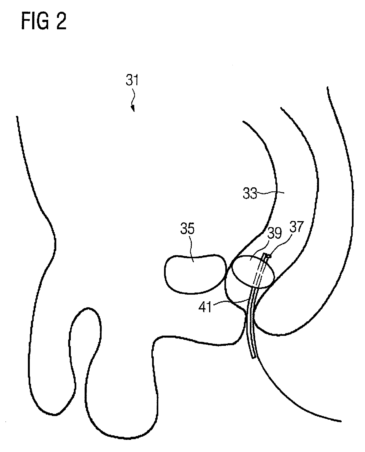
[0014]In one embodiment, the sensor for the pressure measurement is in the intestine. Pressure fluctuations that are due to intestinal gases or movement of intestinal gas masses can be measured. Radiation treatment procedures that are performed in the region of the intestine may be improved. Radiation treatment procedures that performed in the region of the intestine may include, for example, radiation treatments of the prostate, in the lower abdomen, and in the abdomen. The pressure measurement may take place in other hollow organs, such as the bladder, the lungs, the stomach, or other hollow organs.
[0015]In one embodiment, the sensor may be introduced rectally into the intestine, which may provide an easy access route that allows unproblematic placement of the sensor in a patient.
[0018]The sensor may be disposed on an inflatable balloon. An inflatable rectal balloon, for example, may reinforce the immobilization of organs, such as the prostate.

Problems solved by technology

The interaction of the treatment beam with the tissue causes the death of the tissue irradiated.

Method used


Image

  • Control unit and method for controlling a radiation therapy system, and radiation therapy system
  • Control unit and method for controlling a radiation therapy system, and radiation therapy system
  • Control unit and method for controlling a radiation therapy system, and radiation therapy system

Examples


Embodiment Construction

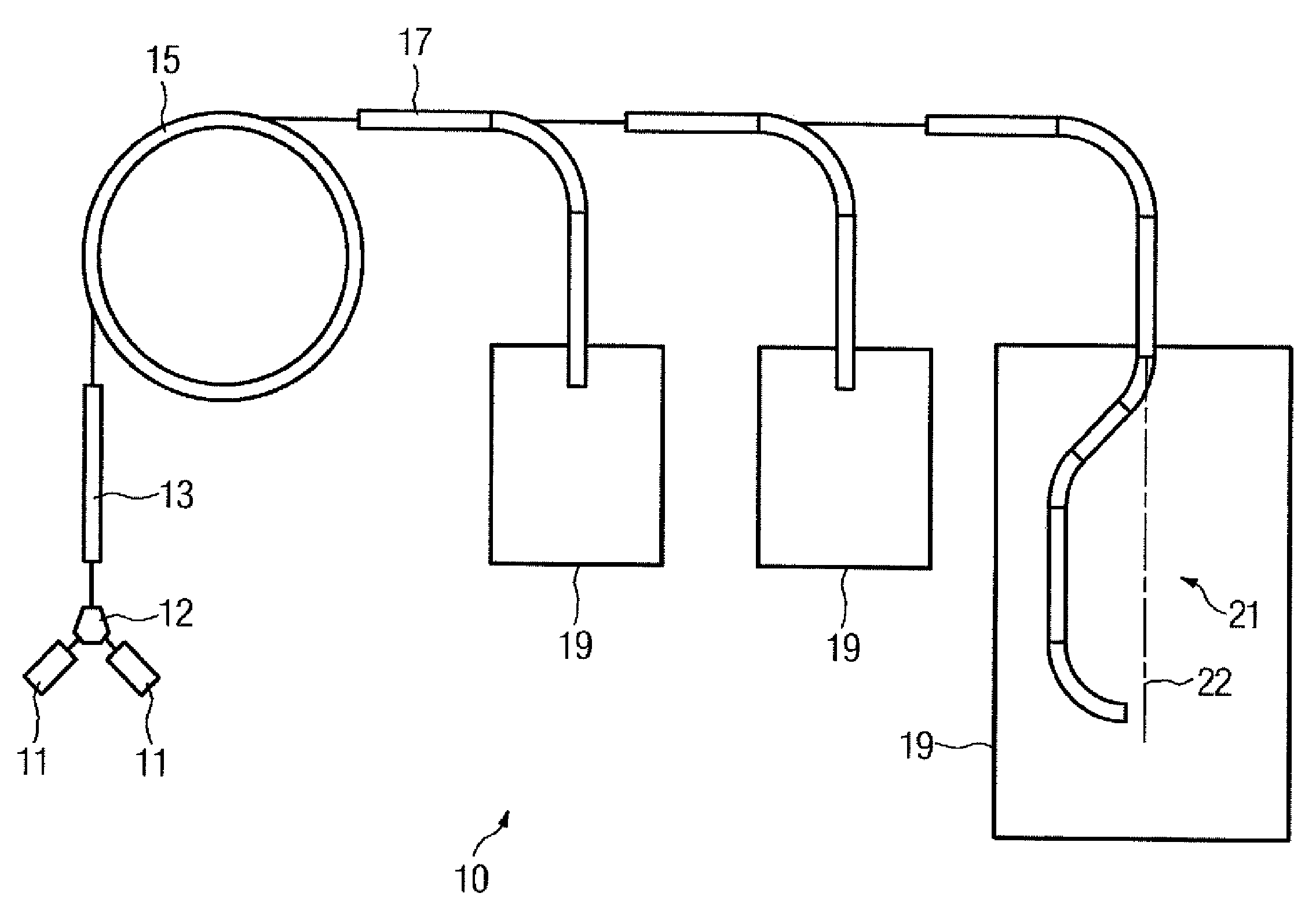
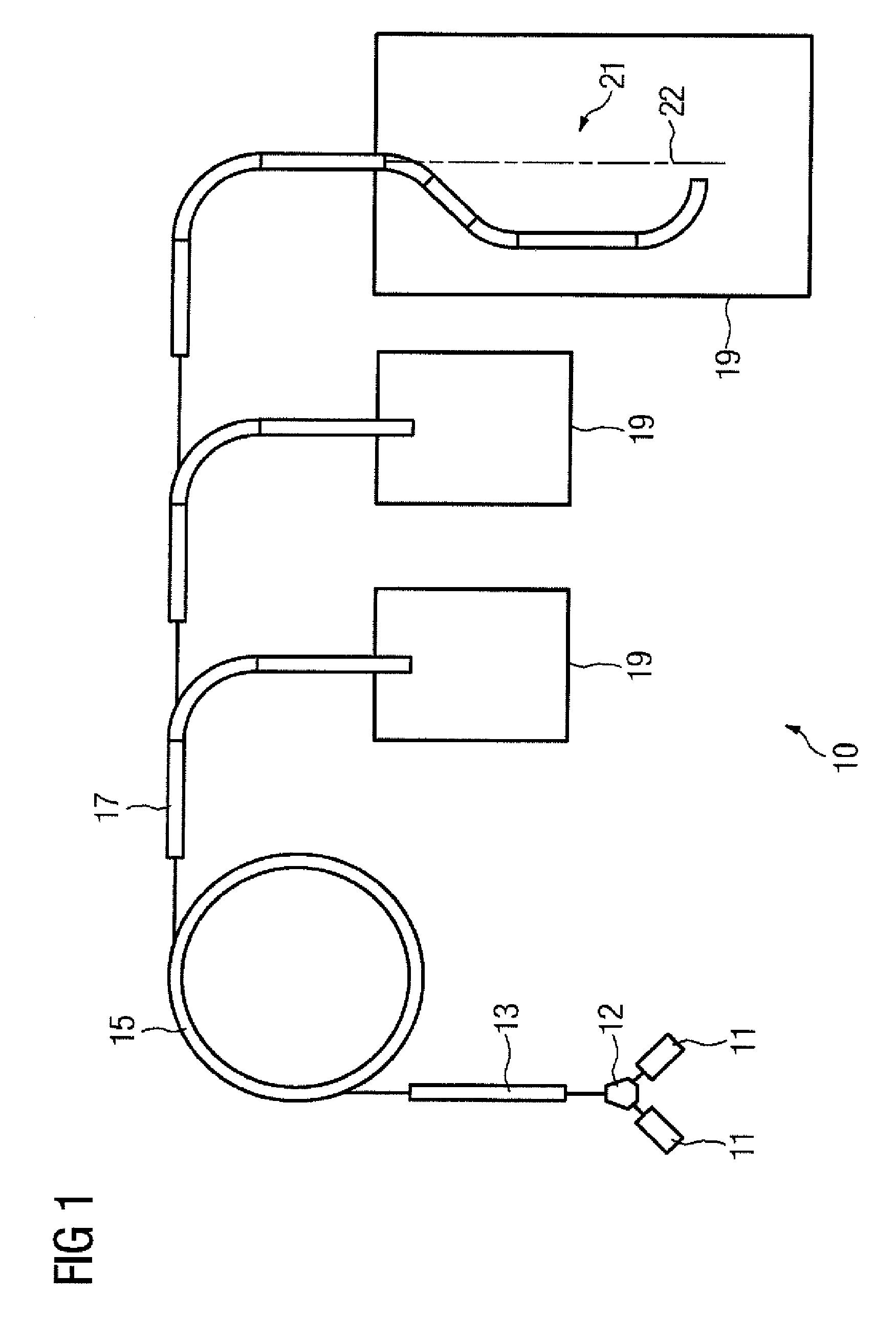
[0030]FIG. 1 shows a particle therapy system 10. The particle therapy system 10 may be used to irradiate a body, such as tissue diseased by tumor, with a particle beam.

[0031]The particle beam may include ions, such as protons, pions, helium ions, carbon ions, or other types of ions. The particles may be generated in a particle source 11. As shown in FIG. 1, the system 10 may include two particle sources 11 that generate two different types of ions. It is possible to switch rapidly between the two types of ions. A switching magnet 12 may, for example, be used to switch rapidly between the two types of ions. The switching magnet 12 may be disposed between the ion sources 11 and a preaccelerator 13. As an example, the particle therapy system 10 may be operated with protons and carbon ions simultaneously.

[0032]The ions generated by the ion sources or one of the ion sources 11 and optionally selected using the switching magnet 12 may be accelerated to a first energy level in the preaccel...


PUM


Abstract

A control system for controlling a radiation therapy system is provided. The control system includes a sensor operable to measure a pressure in the interior of a body; and a control unit operable to output a control signal for a beam interruption unit as a function of a pressure status in the interior of the body.

Description

[0001]The present patent document claims the benefit of the filing date of DE 10 2007 026 516.8, filed Jun. 8, 2007, which is hereby incorporated by reference.BACKGROUND[0002]The present embodiments relate controlling a radiation therapy system.[0003]Radiation therapy is used to treat diseases, such as tumors. During radiation therapy, radiation beams are aimed at a target volume (tissue), which is to be irradiated, of a body. During particle therapy, protons, carbon ions, or other ions, for example, are accelerated to high energy levels and aimed at the tissue to be irradiated. Other types of beams, such as electron or X-ray beams, can be used for the radiation treatment. The interaction of the treatment beam with the tissue causes the death of the tissue irradiated.[0004]To irradiate a target volume as precisely as possible, the treatment beam outputs energy as much as possible in the target volume. The surrounding tissue is spared from the treatment beam output energy. The target...

Claims


Application Information

Patent Timeline
IPC IPC(8): A61B6/00
CPCA61N5/1049A61N5/1067A61N2005/1051
Inventor RIETZEL, EIKE
Owner SIEMENS AG
Learn More