Photosterilization Reactor

a technology of photosterilization reactor and reactor body, which is applied in the direction of food preservation, water/sludge/sewage treatment, water treatment parameter control, etc., can solve the problems of incomplete sterilization, low cross-sectional interaction, and inefficient coupling

Inactive Publication Date: 2008-12-11
ALBONIA INNOVATIVE TECH
View PDF17 Cites 27 Cited by
  • Summary
  • Abstract
  • Description
  • Claims
  • Application Information

AI Technical Summary

Benefits of technology

[0025]In another alternative embodiment of the photosterilization reactor, there are provided means for exposing one or more sections of the liquid or gas sterilization flow path to a multiplicity of organic fluoroscopic excitation wavelengths, the wavelengths being generated in situ at the wall(s) of the liquid or gas sterilization flow path within the reactor by means of a selected group of phosphors capable of down-converting a portion of the ultraviolet radiation from the ultraviolet light source, thereby effecting the fluorescence excitation of some of the pathogens that may be contaminating the input liquid or gas, and also if desired, the output liquid or gas, and further there is provided a means for detecting fluorescence from pathogens thereby providing for the direct fluoroscopic detection of pathogens within the reactor itself.
[0026]In some of the preferred embodiments summarized above, the direct fluoroscopic detection of pathogens within the reactor itself allows for the closed-loop control of energization of the ultraviolet light source, as well as the liquid or gas flow rate and feedrate through the reactor, thereby allowing for precise control of the dwell time, exposure time and overall radiation dose provided to the liquid or gas flowing through the reactor.

Problems solved by technology

These prior art systems suffer from a number of drawbacks, the major one being the inefficient coupling of the generated mutagenic radiation into the liquid or gas flow path, thereby lowering the cross-sectional interaction there between.
Such inefficiencies result in, for example, incomplete sterilization, excessive power consumption, shortened component lifetimes, and the like.

Method used


Image

  • Photosterilization Reactor
  • Photosterilization Reactor
  • Photosterilization Reactor

Examples


Embodiment Construction

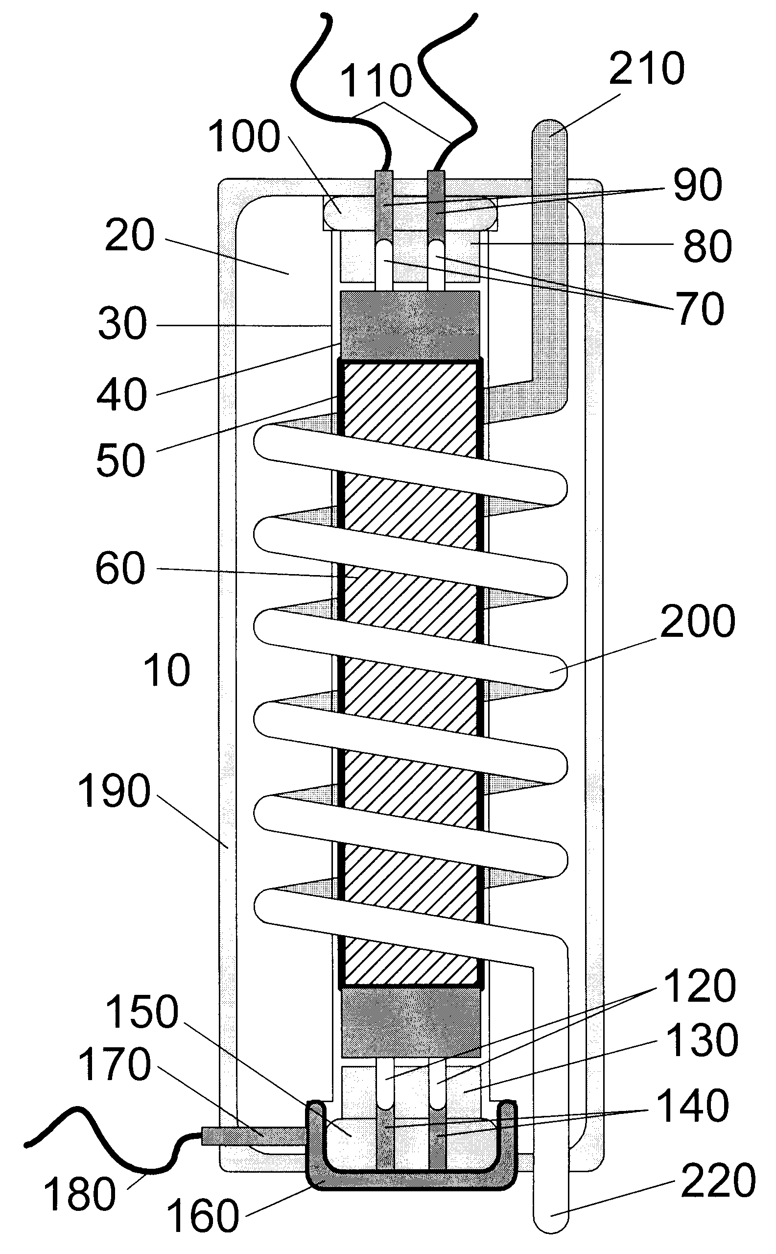
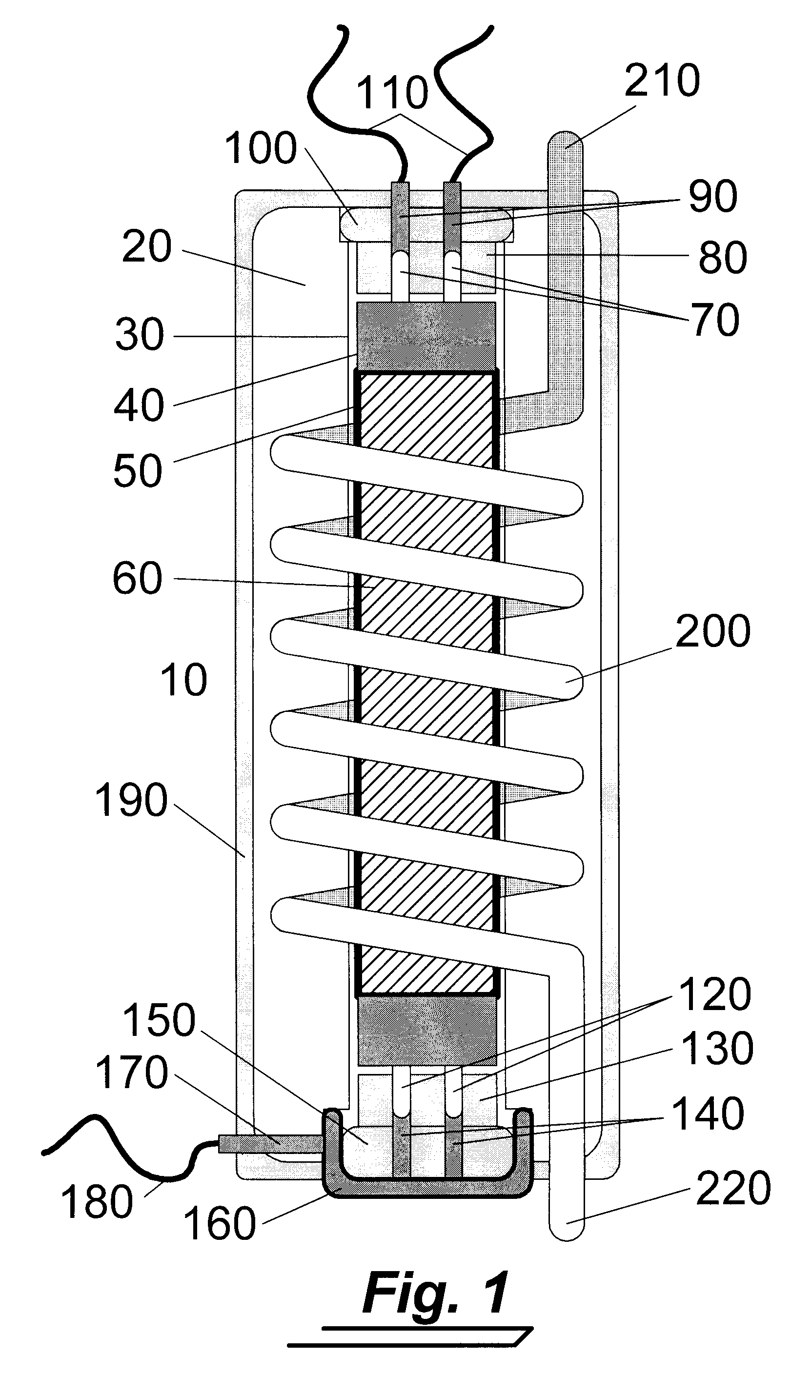
[0035]For a general understanding of the present invention, reference is made to the drawings. In the drawings, like reference numerals have been used throughout to designate identical elements.

[0036]FIG. 1 shows a photosterilization reactor 10. The photosterilization reactor 10 comprises a reactor body 20 made of suitable ultraviolet (UV-C) light transmissive material (minimum absorbance / maximal transmissivity in the region of 240-260 nm) such as fused silica (quartz), or preferentially of a UV transmissive thermoplastic (e.g., CORNING COSTAR®, ZEON ZEONEX® or ZEONOR®, TORAY RAYTELA®, CYP or the like), which are extensively used in the manufacture of UV transmissive wells and cuvettes for fluoroscopy applications.

[0037]Axially disposed in the center of the reactor body 20 is a tubular channel 30 for holding and constraining a suitable ultraviolet light source, here shown to be a low-pressure long-arc mercury vapor (Hg) lamp 40. Other lamps that provide ultraviolet emissions in the ...


PUM


Abstract

A photosterilization reactor for sterilization of a liquid or a gas using ultraviolet light is disclosed that overcomes many of the shortcomings of current ultraviolet sterilization systems and improves the efficiencies of the sterilization process. The photosterilization reactor has an optically coupled flow path for maximizing the cross-sectional interaction between the ultraviolet radiation and the liquid or gas in the flow path, a reactor vessel for the efficient entrapment, reflection and use of the generated and unabsorbed ultraviolet radiation, and operational improvements to the ultraviolet light source, thermal and mechanical shielding of the ultraviolet light source, and electrical safety improvements. The photosterilization reactor may further contain a novel fluoroscopic pathogen detector that provides for real time monitoring of pathogens in the liquid or gas flow path internal to the reactor.

Description

CROSS-REFERENCE TO RELATED PATENT APPLICATIONS[0001]This application claims the benefit of the filing date of U.S. Provisional Patent Application No. 60 / 943,301 filed on Jun. 11, 2007BACKGROUND OF THE INVENTION[0002]1. Field of the Invention[0003]This invention relates generally to an apparatus for sterilizing a liquid or a gas, and more particularly to a novel and improved apparatus that provides for mutagenic sterilization of a liquid or a gas using ultraviolet light.[0004]2. Description of Related Art[0005]The use of certain wavelengths of ultraviolet light, such as UV-C (240-280 nm.) at adequate dosing (energy and exposure time) destroys the Deoxyribonucleic Acid (DNA) structure of many micro-organisms and bacteria, causing mutagenic damage to many pathogens, effectively killing these micro-organisms and bacteria. The use of ultraviolet light is therefore very useful in disinfection of drinking water, fruit juices, milk, other liquids, gases, and some solids or composites such a...

Claims


Application Information

Patent Timeline
Patent Type & Authority Applications(United States)
IPC IPC(8): B01J19/12
CPCA23L3/28A61L2/10B01D53/007B01D2257/91B01D2259/804C02F1/006C02F1/325C02F2201/3223C02F2201/3228C02F2209/36C02F2301/026
Inventor BLUM, DIETER WOLFGANG
Owner ALBONIA INNOVATIVE TECH
Why Eureka
Try Eureka