
Process for combustion of high viscosity low heating value liquid fuels

a liquid fuel, high viscosity technology, applied in the direction of non-combustible gases/liquids, biofeedstock, steam use, etc., can solve the problems of increasing global excess of crude glycerol, increasing the supply of crude glycerol, and not being in a pure form ready, etc., to achieve low heating value, high viscosity, and clean

Active Publication Date: 2008-12-11
NORTH CAROLINA STATE UNIV
View PDF29 Cites 39 Cited by
  • Summary
  • Abstract
  • Description
  • Claims
  • Application Information

AI Technical Summary

Benefits of technology

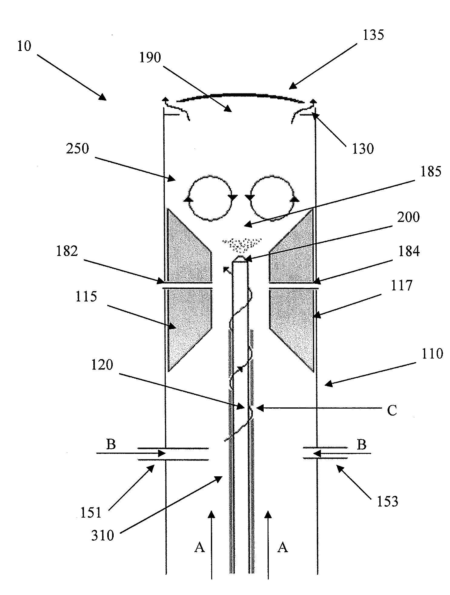
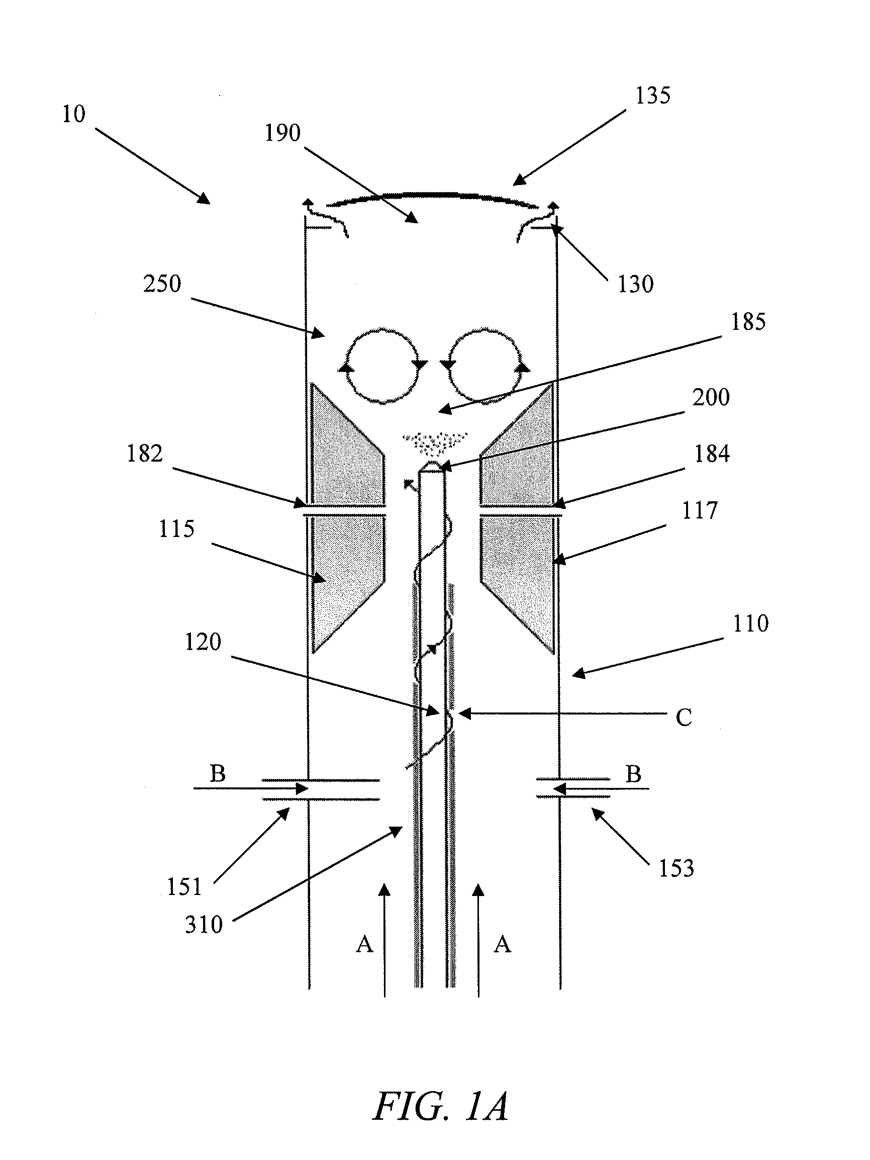
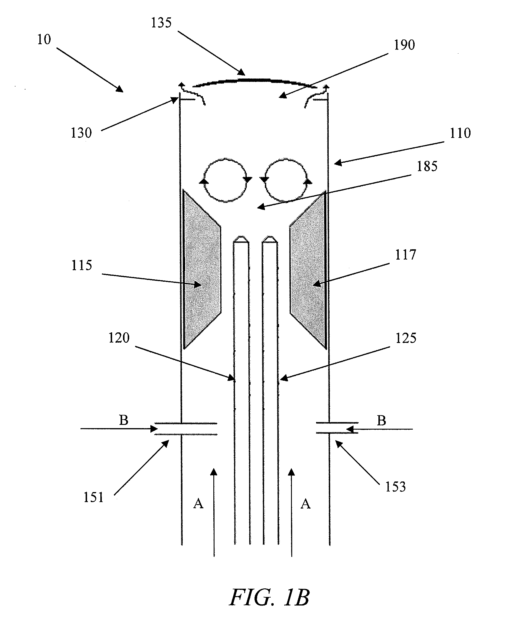
[0019]According to another aspect of the invention, the present invention provides a combustion apparatus that is particularly adapted for the combustion of a high viscosity, low heating value liquid fuel. In particular, the apparatus is useful for the combustion of a liquid fuel having an ambient viscosity of greater than 15 cSt and having a heating value in the range of about 10 MJ / kg to about 75 MJ / kg.
[0023]The inventive apparatus is particularly characterized by the various components used to increase necessary air flow to the combustion chamber, as well as maintaining proper heat and air circulation within the combustion chamber. For example, the apparatus may include one or more zonal restrictors that modify the inner geometry of the apparatus so as to form an expansion zone downstream from the atomizer. Such an expansion zone can be particularly useful to increase sustainability of the glycerol-fueled flame. All of the air flow directing components described above can be particularly beneficial to form a recirculation zone above the atomizer nozzle and within the combustion chamber that recirculates the atomized liquid fuel particles within the combustion chamber to improve total combustion of all fuel particles and minimize fuel particle losses through the exhaust.

Problems solved by technology

As seen by the above multiple possible uses, glycerol is a marketable commodity; however, recent increases in the production of waste glycerol, such as in the production of biofuels, has led to an ever-increasing supply of crude glycerol, which is not in a pure form ready for such uses.
Rather, crude glycerol must undergo refining and other purification steps to provide glycerol of sufficient purity for marketability, and such necessary treatments are generally found to be cost prohibitive.
Moreover, as industrialized nations attempt to move from fossil fuels to more sustainable alternatives, there is an increasing global excess of crude glycerol.
Previous attempts to use waste glycerol as a heating fuel have had limited success and lacked true cost benefit.
For example, there has been a long-standing fear that combustion of glycerol releases toxic acrolein gas unless carried out at a sufficiently high temperature.
Moreover, scholars in the field have theorized that complete and clean combustion of glycerol by-product requires a burning temperature in excess of 1,000° C. and a relatively long mean residence time in the combustion chamber.
Previous attempts to burn glycerol simply have not been able to overcome the safety and technical problems.

Method used


Image

  • Process for combustion of high viscosity low heating value liquid fuels
  • Process for combustion of high viscosity low heating value liquid fuels
  • Process for combustion of high viscosity low heating value liquid fuels

Examples


example 1

Combustion of Glycerol

[0125]A combustion apparatus similar to that illustrated in FIG. 1A was used to achieve sustained combustion of glycerol. Initially, the combustion chamber of the apparatus was pre-heated using propane as a pre-heating fuel. The propane was provided with axial air flow at a rate of 30 standard liters per minute (SLPM) and tangential air flow at a rate of 150 SLPM creating a swirl number calculated to be 17.6 and a Reynolds number of 2,200. Propane flow was started at a rate of 15-20 SLPM and the fuel was ignited.

[0126]Air flow through the atomization nozzle was gradually increased from zero to 18 SLPM, avoiding providing an airflow that would extinguish the propane flame. The combustion chamber was heated with the propane flame until the top of the flame enclosure glowed bright red, indicating the temperature was between about 80° and about 1,000° C.

[0127]Glycerol was pumped through the atomization nozzle, beginning at a rate of about 1 gram per second, and the...

example 2

Emissions Testing

[0128]Emissions from glycerol combustion as described in Example 1 were collected and tested to determine concentrations of various emissions components. Presence of acrolein and other aldehydes was tested using DNPH (2,4-dinitrophenyl-hydrazine) cartridges and high performance liquid chromatography (HPLC). Test cartridges containing a porous plug of DNPH were purchased from a commercial vendor. In practice, exhaust from the glycerol combustion was collected and forced through the DNPH cartridge via low air pressure. Testing functioned that that any ketone or aldehyde compounds present in the exhaust reacted with the DNPH and were retained in the cartridge plug. The DNPH plug was eluted in acetonitrile, and the solution was subjected to HPLC analysis to quantify the mass of particular DNPH derivatives present. Aldehyde concentration was calculated using the mass measurement from the HPLC analysis compared with the volume of exhaust gas that was originally pulled thr...


PUM


Abstract

The present invention is directed to a process for the clean and convenient combustion of high viscosity liquid fuels, such as glycerol, as well as an apparatus useful for carrying such processes. In certain embodiments, the invention provides a process for glycerol combustion comprising providing a combustion apparatus with a glycerol combustion chamber that facilitates reflective heating, pre-heating the glycerol combustion chamber, atomizing the reduced viscosity glycerol, and combining the atomized glycerol with air in the glycerol combustion chamber to thereby completely combust the glycerol. In one embodiment, such as when using a pressure-atomizing nozzle, the inventive method may further comprise treating the glycerol to reduce the glycerol viscosity.

Description

CROSS-REFERENCE TO RELATED APPLICATIONS[0001]The present application claims priority to U.S. Provisional Patent Application No. 60 / 942,290, filed Jun. 6, 2007, which is incorporated herein by reference in its entirety.FIELD OF THE INVENTION[0002]The present invention is directed to processes for combusting high viscosity liquid fuels. In particular, the invention is directed to a process for the clean and efficient combustion of glycerol.BACKGROUND[0003]Glycerol is a long known chemical compound having the structure shown in the formula below.[0004]Glycerol, which is also known as glycerin or propane-1,2,3-triol, is in the general category of polyol compounds (i.e., compounds containing multiple hydroxyl groups) and finds application in many fields. For example, glycerol is used in many medical, pharmaceutical, and personal care preparations as a lubricant and a humectant, as an organic synthesis building block, as a food additive (e.g., humectant, solvent, sweetener softener, fille...

Claims


Application Information

Patent Timeline
IPC IPC(8): F23C5/32F23C1/08F23D11/00F23K5/00
CPCF23C2900/99009F23D11/24F23D11/404Y02E20/12F23D11/448F23D2900/11403F23D2900/14124F23D11/446F23D14/126Y02P30/20
Inventor ROBERTS, WILLIAM L.METZGER, BRIANTURNER, TIMOTHY L.
Owner NORTH CAROLINA STATE UNIV
Learn More