
Coating composition

Inactive Publication Date: 2008-12-18
RICHARDSON ALEXANDER STEWART +1
View PDF4 Cites 4 Cited by
  • Summary
  • Abstract
  • Description
  • Claims
  • Application Information

AI Technical Summary

Benefits of technology

[0032]The inventors have found that when a coating according to the present invention is applied to a surface, and the coated surface is exposed to radiant heat, the coating reduces or increases the heat transferred through the surface compared to similar coatings formed from coating compositions not containing particles of cellulose.
[0033]For example, when a coating according to the present invention is applied to the external surfaces of a metal structure, and the structure is exposed to radiant heat, the coating insulates the structure maintaining the interior of the structure at a temperature significantly lower than that of an equivalent structure having a coating formed from a similar coating composition not containing particles of cellulose, or an equivalent structure having no coating on the external surfaces. Further experiments undertaken by the inventors also suggest that if the ambient temperature outside the structure falls below the internal temperature of the structure, the coating on the external surface of the structure serves to facilitate the transmission of heat out of the structure at a more rapid rate than an equivalent structure having a coating on the external surfaces formed from a similar coating composition not containing cellulose particles, or an equivalent structure having no coating on the external surfaces. This is a particularly useful feature for structures such as buildings containing heat generating machinery, such as electric motors, welding bays or the like.
[0034]When the coating is a plastic film applied to a glass surface such as a window, and the coated surface exposed to radiant heat, the inventors have found that the coating increases the heat transferred through the surface compared to a similar plastic film coating not containing cellulose particles.
[0035]The inventors have also surprisingly found that the smaller the average particle size of the cellulose particles dispersed in the coating composition, the lower the proportion of cellulose particles required to be added to the composition to maintain the useful thermal properties of coatings formed from the composition. For example, a paint coating of 200 μm dry film thickness formed from a liquid paint based composition according to the present invention containing 1 g / L of microcrystalline cellulose particles has similar thermal properties to a paint coating formed from a composition containing about 15 g / L of micronised cellulose particles having average size of about 16 μm in a coating of 200 μm dry film thickness. Experiments by the inventors have also demonstrated that the thermal properties of coatings formed from coating compositions containing cellulose particles having an average dry particle size of less than 10 μm is retained as the proportion of cellulose particles in the composition is decreased from 1 g / L to 0.0002 g / L.

Problems solved by technology

Typically, buildings and other structures are insulated using poor thermal conductive materials such as fibreglass and wool.
Each of these additives has been of only limited value in producing thermally insulating paints.
Further, the inclusion of such additives in paint often detracts from the desirable properties of paint, such as its ease of application to surfaces, and the aesthetic appearance of the paint coating.
The described dimensions of the bagasse particles included in the composition make the composition difficult to apply to a surface and may have undesirable effects on the appearance of the paint coating.
Further, the large particle sizes of the silica and bagasse particles used in some embodiments of the invention result in coatings which are likely to suffer from fungal problems.
In some embodiments, this thin layer does not provide adequate protection from moisture reaching the bagasse particles thereby allowing the growth of fungi.
Further, the required thickness of the paint coating to render it effective make the composition an unsuitable product for use in applications where thinner coatings of paint are required, such as interior and exterior house paints and automotive finishes.

Method used


Image

  • Coating composition
  • Coating composition
  • Coating composition

Examples


Embodiment Construction

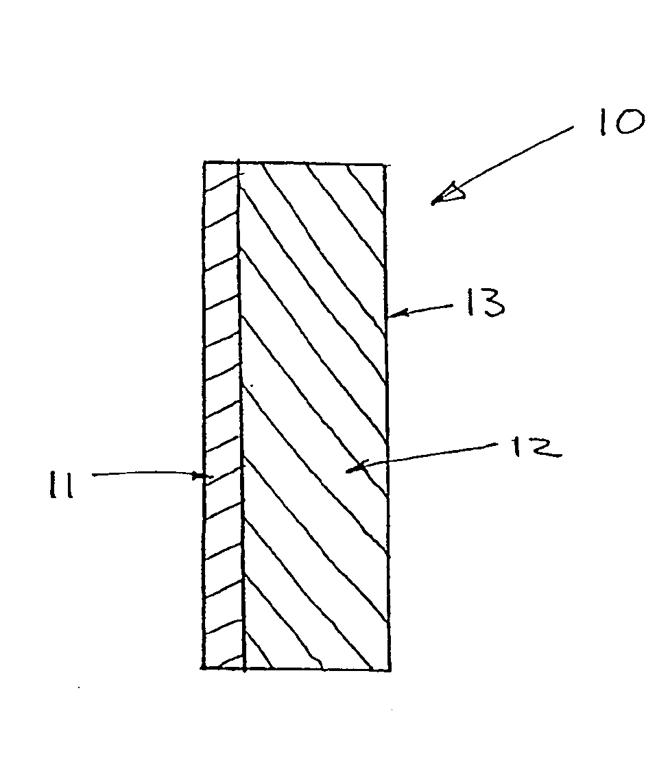
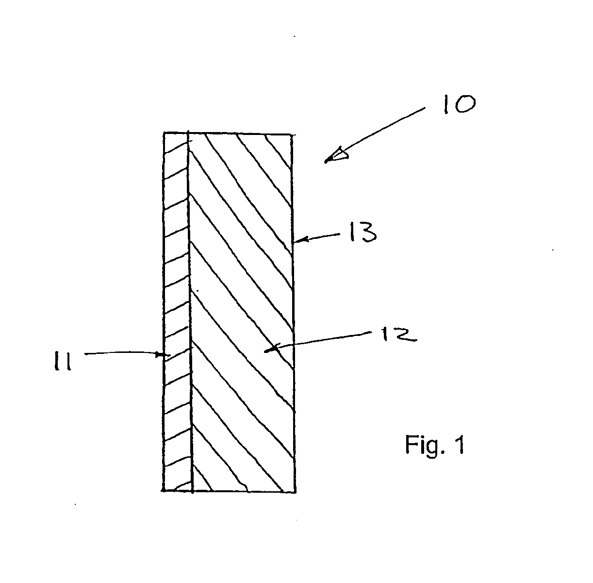
[0051]A cross-sectional view of the samples used in the experiments described herein is shown in FIG. 1. The sample 10 comprises a coating 11 applied to a surface of a substrate 12.

[0052]In all of the experiments described herein, other than the experiment involving window film coatings applied to glass sheets, the substrate 12 consisted of a steel plate of dimensions 200×300×0.9 mm. On one 200×300 mm surface of the steel substrate 12, a coating 11 was formed. The opposite 200×300 mm surface 13 of the steel substrate 12 was coated with a thin layer of conventional black paint. Such samples can be considered representative of coatings applied to structures such as buildings and vehicles.

[0053]To allow a comparison of the performance of coatings formed from coating compositions according to the present invention, experiments were initially undertaken by the present inventors on comparison or reference samples. A coating composition was prepared by adding cellulose particles at a ratio...


PUM

PropertyMeasurementUnit
Densityaaaaaaaaaa
Densityaaaaaaaaaa
Particle sizeaaaaaaaaaa

Abstract

The invention relates to a coating composition comprising (i) a supporting medium, and (ii) a plurality of cellulose particles, having an average dry particle size of less than 10 μm, dispersed in the supporting medium, excluding aqueous coating compositions adapted for application to paper. The invention also relates to a coating composition comprising (i) a supporting medium, and (ii) a plurality of cellulose particles, having an average dry particle size of less than 10 μm, dispersed in the supporting medium in an amount of less than about 5 g / L. The coating compositions of the invention form coatings which have useful thermal properties.

Description

TECHNICAL FIELD[0001]The present invention relates to coating compositions which form coatings which have useful thermal properties.BACKGROUND ART[0002]It is well understood that heat can be transmitted from one place to another by three mechanisms, namely radiation, conduction and convection.[0003]The benefits of insulating buildings and other structures have long been understood. Typically, buildings and other structures are insulated using poor thermal conductive materials such as fibreglass and wool. These materials are typically used in the walls and ceilings of structures to retard the transfer of heat into the structure during warmer months, and to retard the transfer of heat out of the structure during cooler months.[0004]A number of attempts have been made to develop paints that effectively retard the transfer of heat through a surface to which the paint has been applied. For example, materials such as sodium bicarbonate and steric acid, potassium titanate fibres, glass fri...

Claims


Application Information

Patent Timeline
IPC IPC(8): B32B5/16C09D101/02B05D7/24B05D7/00B32B27/20C09D5/00C09D5/32C09D7/65C09D201/00
CPCC08L1/02C09D7/125C09D7/1283Y10T428/253Y10T428/25Y10T428/277Y10T428/27Y10T428/2982Y10T428/273C09D7/65C09D7/69Y10T428/31993Y10T428/31971C09D101/02
Inventor RICHARDSON, ALEXANDER STEWARTSMYTH, JOHN ANDREW
Owner RICHARDSON ALEXANDER STEWART
Learn More