Hybrid etch chamber with decoupled plasma controls

Inactive Publication Date: 2009-01-01
INTEVAC
View PDF35 Cites 114 Cited by
  • Summary
  • Abstract
  • Description
  • Claims
  • Application Information

AI Technical Summary

Benefits of technology

[0010]The following summary of the invention is provided in order to provide a basic understanding of some aspects and features of the invention. This summary is not an extensive overview of the invention and as such it is not intended to particularl

Problems solved by technology

The abundance of small ions, such as fluorine, adversely effect the plasma etch process.
Some of the issues facing current etch chamber technology includes inability to independently control gas dissociation, inability to obtain high selecti

Method used


Image

  • Hybrid etch chamber with decoupled plasma controls
  • Hybrid etch chamber with decoupled plasma controls
  • Hybrid etch chamber with decoupled plasma controls

Examples


Embodiment Construction

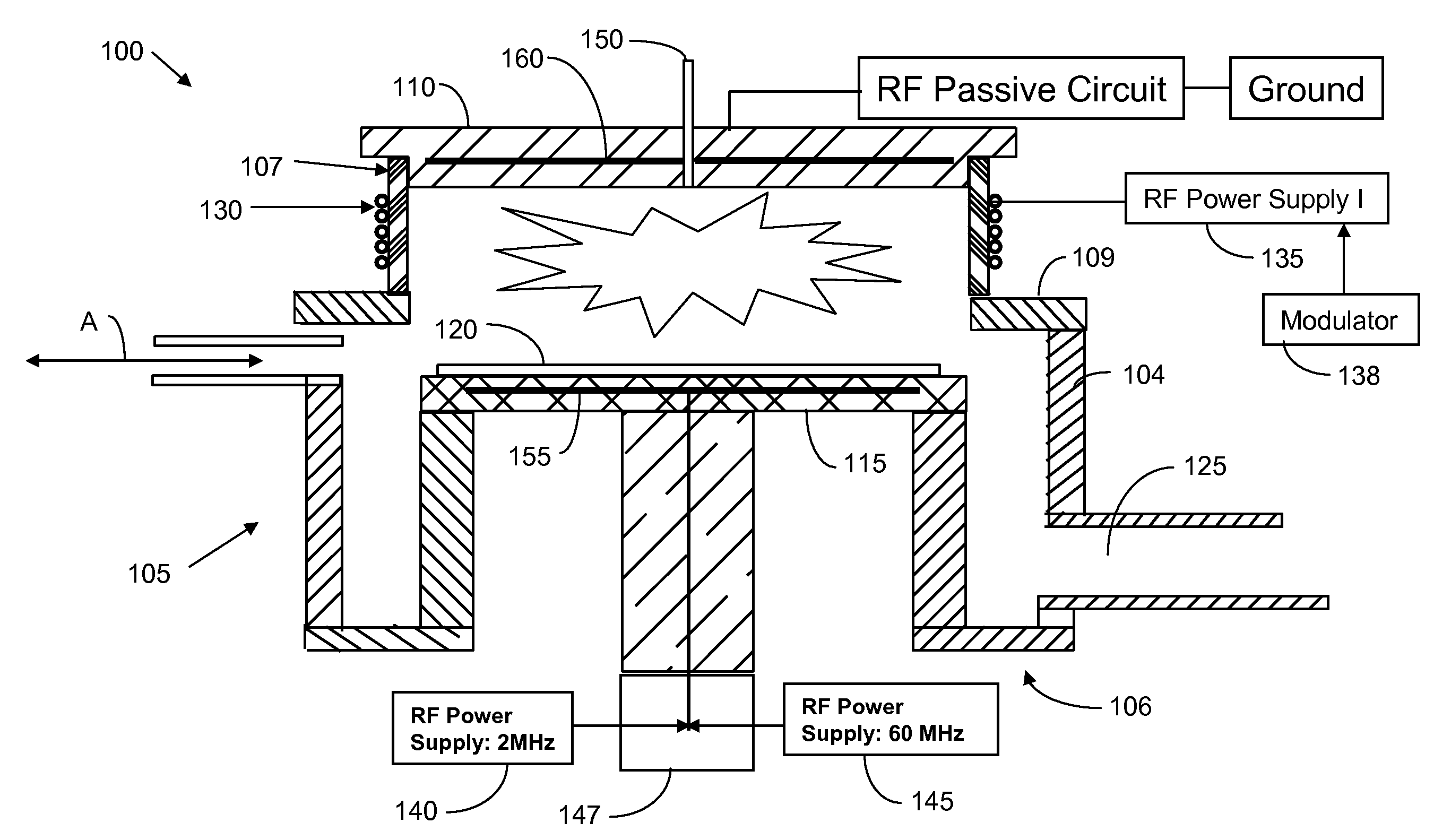
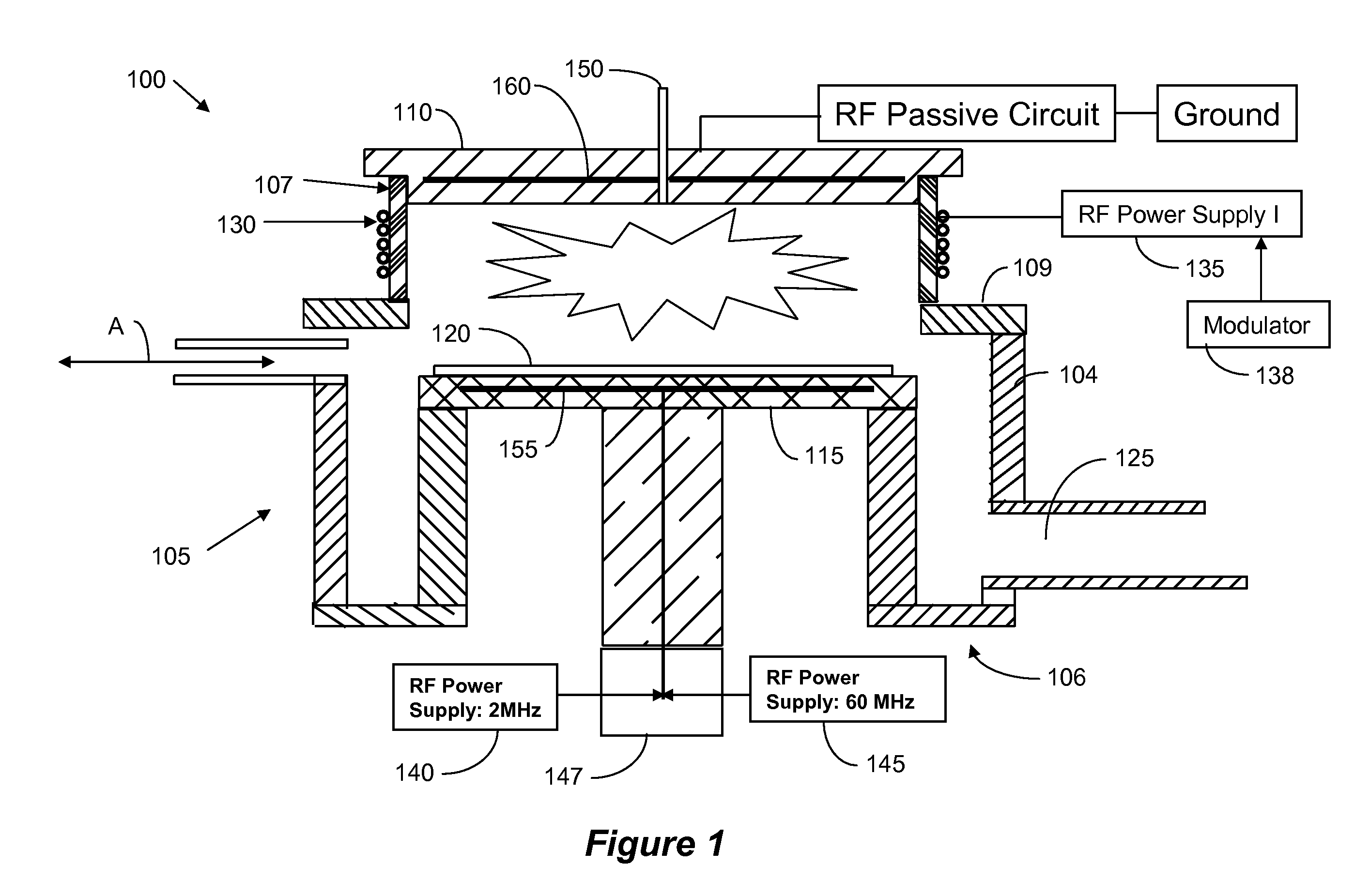
[0033]The subject invention provides an etch chamber that enables advance etch processes by enabling independent control of gas dissociation, plasma density, and ion energy. The current inventors have discovered that an improved control of plasma processing parameters can be obtained by combining an inductive-coupling antenna driven at one frequency with dual frequency bias RF power. Moreover, the subject inventors have discovered that the improved control is further enhanced by having the power to the antenna modulated.

[0034]Equation 1 estimates the relationship of the etch rate to the various elements of the plasma.

Eq.1:ERgross=k0Γexp(-EakT)+Yp(1-Θ)Γ++YIEΘΓ+

Wherein—k0 and Ea are rate parameters for spontaneous chemical etching; Γ is the neutrals flux; Yp is the physical sputtering yield; Φ is the fraction of surface sites occupied by the reactant species; Γ+ is the Ion flux; and YIE is the ion enhanced etching yield while the surface is saturated with reactant species. The first t...


PUM

PropertyMeasurementUnit
Frequencyaaaaaaaaaa
Frequencyaaaaaaaaaa
Frequencyaaaaaaaaaa

Abstract

A dielectric etch chamber and method for improved control of plasma parameters. The plasma chamber comprises dual-frequency bias source that capacitively couples the RF energy to the plasma, and a single or dual frequency source that inductively couples the RF energy to the plasma. The inductive source may be modulated for improved etch uniformity.

Description

BACKGROUND[0001]1. Field of the Invention[0002]The subject invention relates to an etch chamber having independent control of plasma parameters.[0003]2. Related Art[0004]Plasma etch chambers have been used in the semiconductor art for years. In general, plasma etch chambers can be divided into types by application and by plasma source. With respect to application, plasma chambers are divided into conductor etchers, those that are used to etch polysilicon and metals, and dielectric etchers, those that are used for etching insulators, such as silicon oxide, undoped silicate glass (USG), boron-phosphorous silicate glass (BPSG), etc. As for plasma sources, the two main types relating to the subject application are capacitively coupled and inductively coupled chambers. As is well known, a capacitively coupled chamber is constructed using a cathode and an anode and applying an RF potential there-between. On the other hand, in inductively coupled chambers the RF energy is coupled into the ...

Claims


Application Information

Patent Timeline
IPC IPC(8): H01L21/461H01L21/306
CPCH01J37/32091H01J37/32165H01J37/321H01J37/32862
Inventor YANG, JANG GYOOBARNES, MICHAELBLUCK, TERRY
Owner INTEVAC
Why Eureka
Try Eureka