Exhaust Gas Purification System of Internal Combustion Engine

a technology of exhaust gas purification system and internal combustion engine, which is applied in the direction of machines/engines, exhaust treatment electric control, separation processes, etc., can solve the problems of catalyst carrying amount, catalyst function to decrease or catalyst to clog, active site of catalyst covered, etc., to prevent the effect of catalyst exhaust gas purification action

Inactive Publication Date: 2009-01-08
TOYOTA JIDOSHA KK
View PDF20 Cites 5 Cited by
  • Summary
  • Abstract
  • Description
  • Claims
  • Application Information

AI Technical Summary

Benefits of technology

[0005]Therefore, the present invention has as its object the provision of an exhaust gas purification system of an internal combus

Problems solved by technology

Therefore, when the exhaust gas contains a large amount of formaldehyde, if feeding urea to the catalyst, not only can the urea be effectively utilized for NOx reduction, but also a large amount of urea resin is formed on the catalyst and therefore the active sites of the catalyst are liable to be covered and the catalyst function to decreases or the catalyst to clog.
If the cell pitch of the catalyst is made larger to suppress this clogging, the catalyst carried amount is liable to decrease or the contact frequency of the catalyst is liable to decrease.
In any case,

Method used


Image

  • Exhaust Gas Purification System of Internal Combustion Engine
  • Exhaust Gas Purification System of Internal Combustion Engine
  • Exhaust Gas Purification System of Internal Combustion Engine

Examples


Embodiment Construction

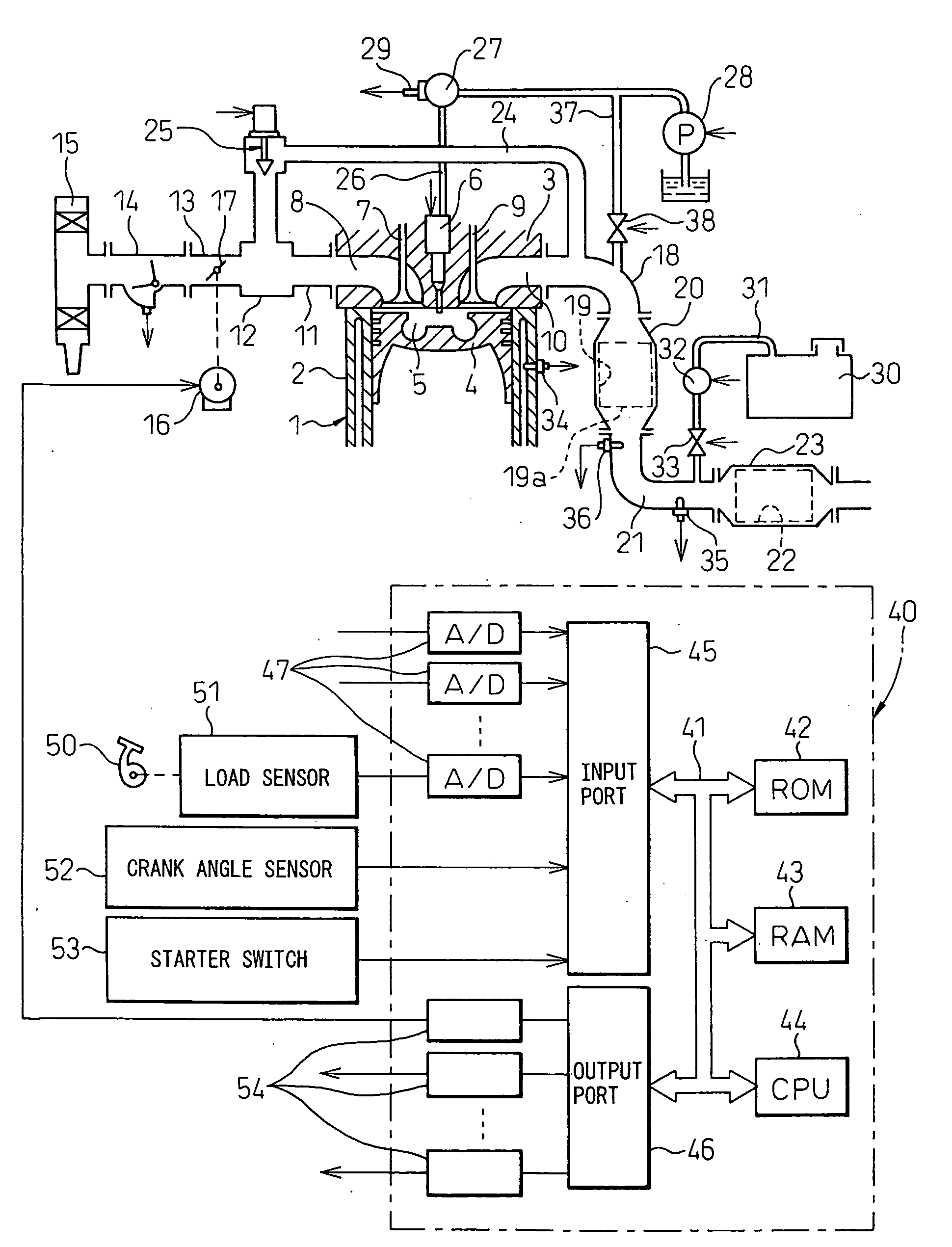
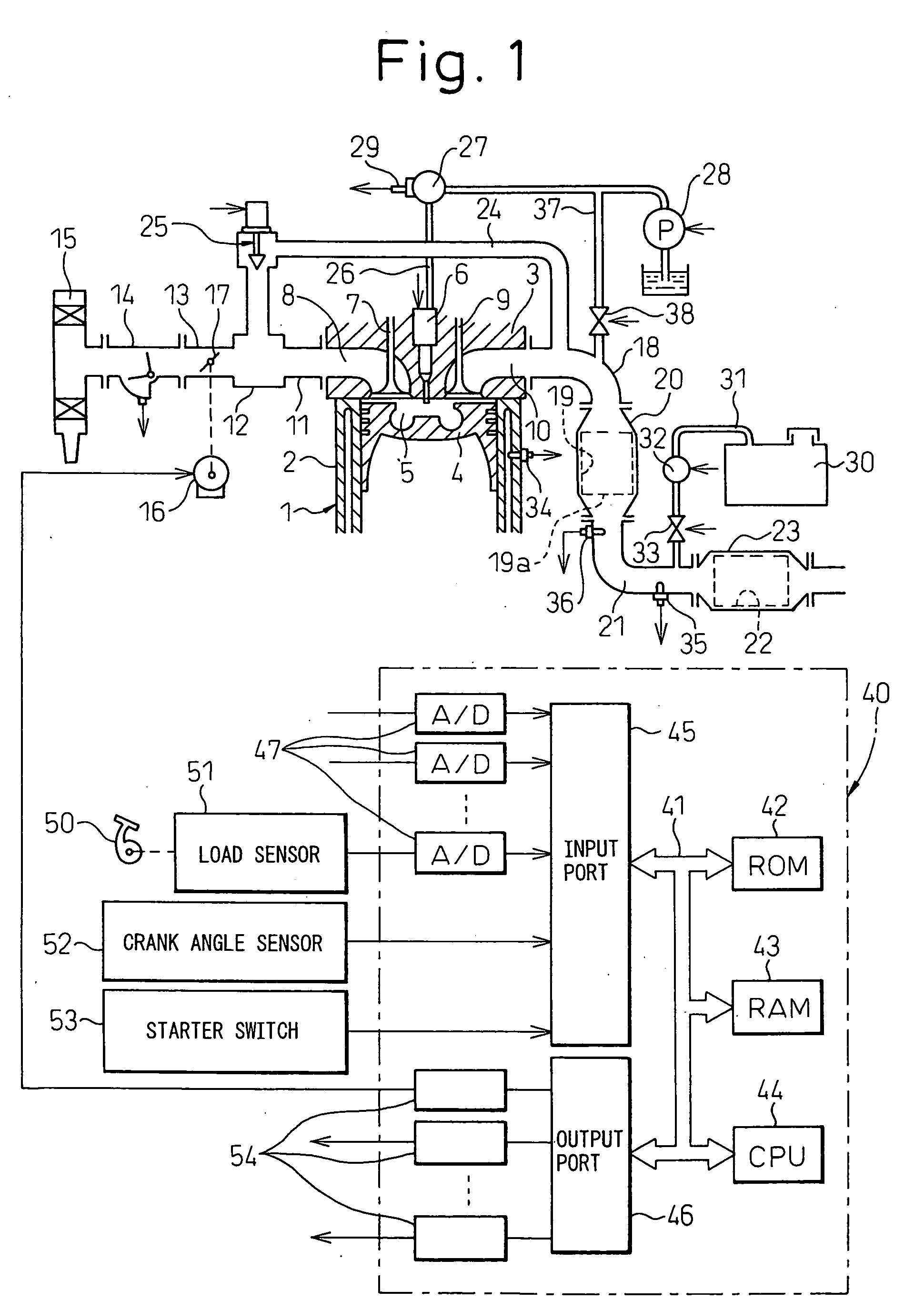
[0009]FIG. 1 shows the case of application of the present invention to a compression ignition type internal combustion engine. Note that the present invention can also be applied to a gasoline engine.

[0010]Referring to FIG. 1, 1 indicates an engine body, 2 a cylinder block, 3 a cylinder head, 4 a piston, 5 a combustion chamber, 6 an electrically controlled fuel injector, 7 an intake valve, 8 an intake port, 9 an exhaust valve, and 10 an exhaust port. The intake port 8 is connected to a surge tank 12 through a corresponding intake tube 11, while the surge tank 12 is connected through an intake duct 13 and an air flow meter 14 to an air cleaner 15. Inside the intake duct 13, a throttle valve 17 driven by a step motor 16 is arranged.

[0011]On the other hand, the exhaust port 10 is connected to an inlet of a first catalytic converter 20 housing the catalyst 19 through an exhaust manifold 18, while the outlet of the first catalytic converter 20 is connected through an exhaust pipe 21 to a...


PUM

PropertyMeasurementUnit
Timeaaaaaaaaaa

Abstract

A catalyst suited for reducing NOx in an exhaust gas by ammonia in the presence of excess oxygen is arranged in an engine exhaust passage. An aqueous urea solution is fed from a flow addition valve onto a catalyst, part of the urea fed to the catalyst is stored in the catalyst, and the ammonia generated from the urea stored in the catalyst is used to reduce the NOx in the exhaust gas. At the time of engine startup, at the time of cold operation, and at the time of increase of the HC amount, it is determined that the amount of formaldehyde in the exhaust gas flowing into the catalyst exceeds the allowable amount, and, at this time, the feed of urea to the catalyst is prohibited.

Description

TECHNICAL FIELD[0001]The present invention relates to an exhaust gas purification system of an internal combustion engine.BACKGROUND ART[0002]Known in the art is an internal combustion engine arranging a catalyst suitable for reducing NOx in exhaust gas by ammonia in the presence of excess oxygen in an engine exhaust passage, feeding an aqueous urea solution to this catalyst, storing part of the urea fed to the catalyst in the catalyst, and using the ammonia generated from the urea stored in the catalyst to reduce the NOx in the exhaust gas (see Japanese Patent Publication No. 3685063).[0003]However, the exhaust gas sometimes contains formaldehyde. When this formaldehyde reacts with the urea stored in the catalyst, urea resin is generated. Therefore, when the exhaust gas contains a large amount of formaldehyde, if feeding urea to the catalyst, not only can the urea be effectively utilized for NOx reduction, but also a large amount of urea resin is formed on the catalyst and therefor...

Claims


Application Information

Patent Timeline
IPC IPC(8): F01N9/00
CPCB01D53/9409B01D2251/2067F01N3/0814F01N3/208F01N9/00F01N2560/02Y02T10/24F01N2560/14F01N2610/02F01N2610/146F01N2900/1622Y02T10/47F01N2560/06Y02T10/12Y02T10/40B01D53/86F01N3/08F01N3/20F01N3/28
Inventor ITOH, KAZUHIRO
Owner TOYOTA JIDOSHA KK
Why Eureka
Try Eureka