
Breathing air filtration devices

a technology which is applied in the field of filtration device and breathing air filtration device, can solve the problems of increasing the risk of contamination of ambient air in certain specialized environments, increasing the tendency for carbon dioxide buildup, and reducing the effect of filtration efficiency

Inactive Publication Date: 2009-01-08
AIRWARE HLDG
View PDF88 Cites 46 Cited by
  • Summary
  • Abstract
  • Description
  • Claims
  • Application Information

AI Technical Summary

Benefits of technology

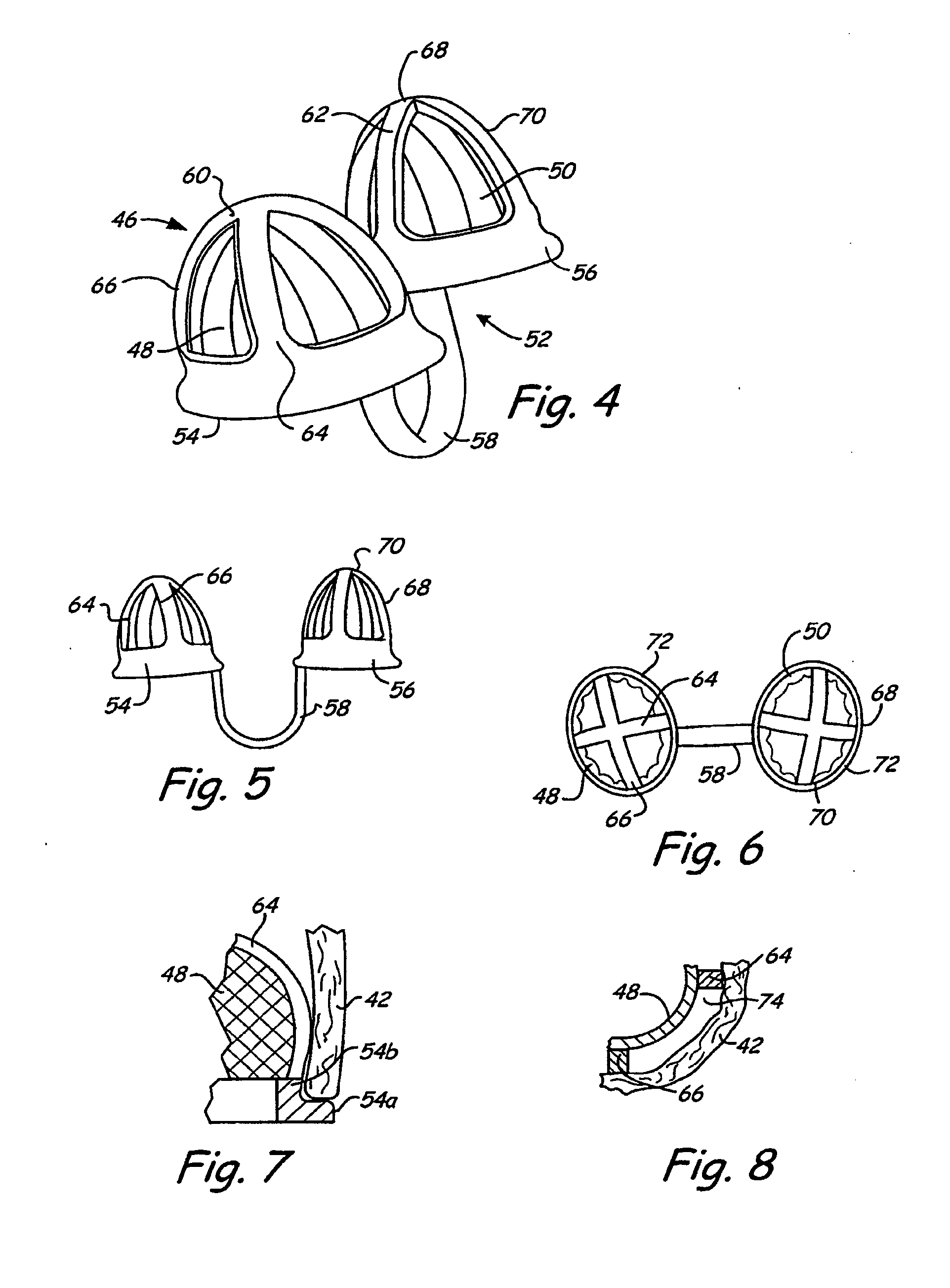
[0012]Preferably, each filtering medium in its working position is spaced apart from the septum and from the nasal wall defining the associated nasal cavity. This result may be achieved by using a filtering medium that is substantially self-supporting, or by disposing an open frame between a more pliable filtering medium and the nasal wall. In either event, this arrangement provides increased comfort, and facilitates the flow of incoming air along the inside surface of the nasal wall, to effectively warm and moisturize the air when the filtering device is in place.
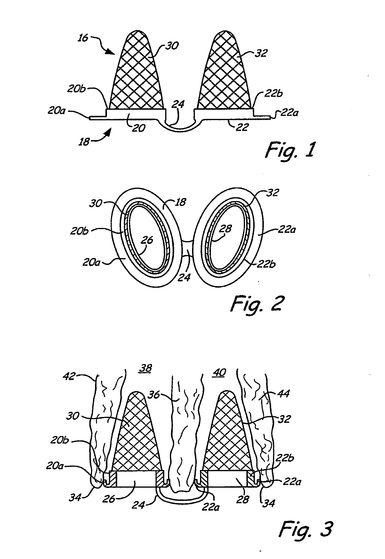
[0014]Conical or ellipsoidal filtering media afford increased area available for filtration as compared to filtering media with planar surfaces at the nasal cavity entrance. This advantage can be appreciated when considering the surface area of a hemisphere, as compared to a disk of the same radius. The hemisphere surface area is twice as large. The ellipsoidal and elliptical / conical filtering media can be configured to enhance the advantage, providing effective surface areas more than twice the area of the entrance to the nasal cavity. Additionally, the filtering media itself can be slanted at any angle.
[0015]The present invention may be embodied in a two-stage device, in which a first screening component is mounted with respect to the first base member and disposed proximally of the first filtering medium, and a second screening component is similarly mounted with respect to the second base member. The screening component can comprise a relatively coarse (larger porosity) activated charcoal filter intended to remove odors and larger particles. This prevents the larger particles from reaching the downstream filtering media, extending their useful life.
[0016]In certain environments, it is vital to insure against inhaling contaminants through the mouth as well as the nose. To this end, the device is augmented with a third base member positionable against the face in surrounding relation to the mouth to form an opening through which air can enter the mouth, and a third filtering medium mounted with respect to the third base member and dispose over the opening. If desired, the third filtering medium can be concaved-convex and project away from the mouth in the proximal direction. A flexible band or other retainer is used to releasably maintain the third base member against the user's face.
[0017]As compared to a mask filter covering the nose and mouth, the combination of separate nose and mouth filters is less cumbersome, less prone to leakage at the filtering device perimeter, and has a smaller enclosed volume near the face, and therefore is less prone to accumulation of exhaled carbon dioxide. If the user inhales substantially exclusively through the nose, problems due to carbon dioxide accumulation are avoided altogether.
[0023]Thus in accordance with the present invention, a filtration device insertable into the nasal cavities is easy to use, has a minimal impact on the appearance of the user, and provides more effective and longer-lasting filtration. Improved performance arises in part from the retention of air warming and moisturizing capability when the filtering media are maintained in the spaced-apart relation to the nasal walls. Improved performance also can arise from an enlarged surface area available for filtration, due to a concave-convex shape or truncated conical of the filtering media, and further if desired by forming the media with pleats or corrugations. Finally, the nasal filter can be combined with a filter covering the mouth to provide a filtration system which, compared to a conventional mask, is less prone to perimeter leakage and accumulation of exhaled carbon dioxide.

Problems solved by technology

Certain specialized environments entail a greater risk of contamination in ambient air, e.g., construction sites and mines with respect to particulate matter, and hospitals with respect to viral and bacterial agents.
These masks frequently are ineffective due to perimeter leakage between the mask and face.
Individuals who might benefit from the masks frequently refuse to wear them, due to discomfort or dissatisfaction with the appearance of the mask.
Moreover, the masks tend to trap exhaled carbon dioxide, especially when the mask includes a fine (microporous) filter and forms a tight seal against the face.
The longer the mask is worn, the greater is the tendency for buildup of carbon dioxide.
The user, inhaling increasing amounts of carbon dioxide, is subject to headaches, drowsiness, and nausea, with prolonged exposure causing more severe effects.
In either event the supporting structure, which is impermeable to air flow, presses against the nasal wall and tends to mat the turbinates and nose hairs, thus diminishing the capacity of the nostril to trap particles, and warm and moisten incoming air.
The filtering devices may satisfactorily perform the particle trapping function, but are not well adapted to warm and moisten the incoming air.
The appearance of the filter, and the need for an adhesive, are disadvantages to this approach.
Further, regardless of whether the foregoing nasal filters are mounted outside the nose or inserted into the nasal cavities, they frequently are inconvenient to use and uncomfortable to wear, and fail to provide a reliable sealing engagement with nasal or facial tissue to ensure that incoming air passes through the filtering media.
Finally, the nasal filters afford no protection against intentional or inadvertent inhaling through the mouth.

Method used


Image

  • Breathing air filtration devices
  • Breathing air filtration devices
  • Breathing air filtration devices

Examples


Embodiment Construction

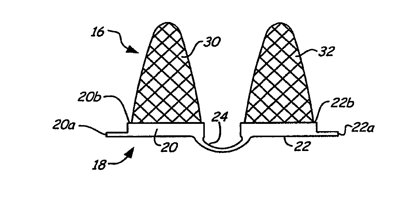
[0058]Turning now to the drawings, there is shown in FIG. 1 a nasal air filtering device 16 insertable into the nasal cavities to filter ambient air as it is inhaled by the user. Device 16 includes a unitary support structure or panel 18, preferably formed of a hypo-allergenic material such as polyvinyl chloride (PVC) or polyurethane. The panel is structurally self-supporting and further is flexible and compliant so that it readily conforms to the anterior surface of the nose, in particular the anterior nares and septum, when device 16 is in use.

[0059]Panel 18 includes a base 20, an opposite base 22, and a connecting member or bridge 24 coupled to the bases to maintain the bases spaced apart from one another a desired distance. Each of the bases is annular—more precisely, generally annular in sense that its profile is somewhat elliptical rather than circular. Bases 20 and 22 have respective closed or endless perimeter regions 20a and 22a, and shoulders 20b and 22b that surround open...


PUM


Abstract

A nasal air filtration device includes a pair of either planar or concave-convex filters, a support structure incorporating a pair of generally annular bases or sleeves for supporting the filters, and a bridge that couples the bases or sleeves to maintain them in a desired spaced-apart relation and to determine a desired angular relationship. The support structure is insertable into the nasal cavities to position the filters within corresponding nasal cavities. Flexible rims maintain the support structure and the filters in spaced-apart relation to the surrounding nasal wall. The filters may be placed within the bases at an angle with respect to the walls of the bases. Also, the filtration device may be flesh tone in color, thereby blending with the skin tone of the user. In some embodiments, a post structure is supplied for supplying a scent or aroma to the wearer.

Description

CROSS REFERENCE TO RELATED APPLICATIONS[0001]This is a continuation-in-part of application Ser. No. 11 / 238,672, filed Sep. 29, 2005, which is a continuation-in-part of application Ser. No. 11 / 077,784, filed Mar. 11, 2005, which is a continuation-in-part of application Ser. No. 10 / 804,995, filed Mar. 19, 2004, now U.S. Pat. No. 7,156,098, each of which is hereby incorporated by reference in its entirety herein.BACKGROUND OF THE INVENTION[0002]The present invention relates to devices and systems for filtering ambient air as it is inhaled, and more particularly to filtration devices and systems that employ filtering media and filtering components insertable into the nasal cavities. There is an increasing need for effective filtration of breathing air, to reduce inhaled quantities of particulates and contaminants such as dust and pollen. In cities and other densely populated regions, there is a greater need for filtering pollutants generated by industrial and vehicle emissions. Certain ...

Claims


Application Information

Patent Timeline
IPC IPC(8): A62B7/10
CPCA61M15/08A61M15/085A62B23/06A61M2210/0618A62B7/10A62B9/06
Inventor DOLEZAL, DAVID M.WILDER, JOHN D.GELFMAN, DANIEL M.
Owner AIRWARE HLDG
Learn More