Switching power supply apparatus

a power supply and switch technology, applied in the direction of electric variable regulation, process and machine control, instruments, etc., can solve the problems of reducing the size of the device, increasing the cost, increasing the power consumption of the standby device, etc., to reduce the audible sounds generated by the isolation transformer and specific to burst oscillation, the effect of reducing the power consumption during the standby

Inactive Publication Date: 2009-01-08
FUJI ELECTRIC CO LTD
View PDF5 Cites 21 Cited by
  • Summary
  • Abstract
  • Description
  • Claims
  • Application Information

AI Technical Summary

Benefits of technology

[0014]The second control mechanism can include a capacitor and charging / discharging mechanism which charges the capacitor at a constant current with the timing of output of the switching-enabled signal, and which discharges the capacitor at a constant current with the timing of output of the switching-enabled signal, and the voltage value of the capacitor can be used as a turn-on pulse width value for the switching element the inclination of the carrier signal set in the first control mechanism can be changed according to the voltage value of the capacitor of the second control mechanism; and, by maintaining the capacitor of the second control mechanism in a fully-charged state, the first control mechanism can be made to operate preferentially.
[0015]The invention provides an apparatus in which power consumption during standby can be reduced, while supplying stabilized power to a microcomputer. Further, power consumption during standby can be reduced, without causing the control power supply voltage to fall below the minimum operating voltage. Still further, audible sounds generated by the isolation transformer and specific to burst oscillation can be reduced, and by use of the present apparatus control circuit can be simplified. Power supplied to the microcomputer can also be further stabilized.

Problems solved by technology

A capacitor with a large static capacitance is physically large, and so impedes efforts to reduce the size of the switching power apparatus, and also leads to cost increases.
Further, in the circuit of FIG. 12, the power consumption of the startup circuit is the product of the voltage difference between the voltage of the DC power supply 1 and the control power supply voltage VCC, and the current flowing in the startup circuit, and tends to cause an increase in the standby power consumption.
Moreover, there is also the problem that when the power supplied to the microcomputer 15 is switched by the switch 17, voltage fluctuations occur at the instant of switching, so that erroneous operation of the microcomputer 15 or similar may occur.
However, when the switching element 2 halts oscillation, there is a sudden change from a state in which current is flowing in the isolation transformer 3 to a state in which no current flows, and so there is the problem that there is less effect in decreasing audible noise.

Method used


Image

  • Switching power supply apparatus
  • Switching power supply apparatus
  • Switching power supply apparatus

Examples


first embodiment

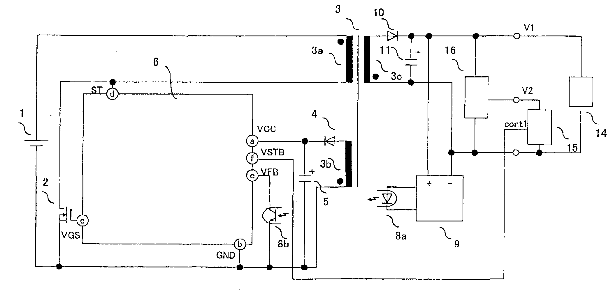
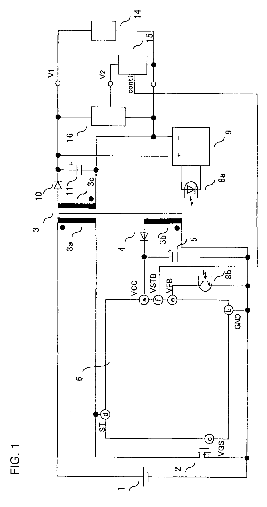
[0029]FIG. 1 shows the circuit configuration of a switching power supply apparatus which represents an aspect of the As shown in the figure, characteristics of this apparatus are the introduction of a switching signal cont1 from the microcomputer 15 into the control circuit 6, and the provision of voltage stabilizing mechanism 16 to stabilize the voltage input to the microcomputer 15; otherwise the configuration is similar to those of FIG. 10 and FIG. 12. As the voltage stabilizing mechanism 16, for example, a chopper control power supply or series regular power supply, or another well-known device, can be used, and the details thereof are omitted.

[0030]The switching signal cont1 from the microcomputer 15 is insulated from the primary side of the transformer by a photocoupler or other means. A similar configuration is employed in each of the following aspects.

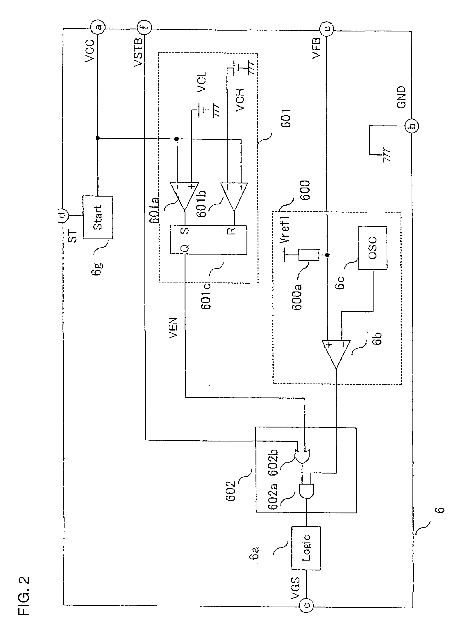
[0031]FIG. 2 is a circuit configuration diagram showing a specific example of a control circuit, and in summary comprises fi...

second embodiment

[0051]FIG. 9 is a configuration diagram showing the invention. A characteristic of this circuit is that the series circuit of switching elements 2a and 2b is connected in parallel with the DC power supply 1; by turning on and off the switching elements 2a and 2b in alternation, series resonance operation is induced in the capacitor 21 and the excitation inductance or leakage inductance of the isolation transformer 3, and resonance energy is supplied to the secondary side of the transformer (resonance-type power supply). An example is shown in which the switching element 2b is driven by the auxiliary windings 3d of the isolation transformer 3; but driving is also possible using a high-withstand voltage IC (IC: integrated circuit) and a pulse transformer.

[0052]In a resonance-type power supply such as shown in FIG. 9, a voltage from the isolation transformer 3 which has been rectified and smoothed, such as for example the DC output voltage V1 and the control circuit power supply voltag...


PUM


Abstract

A switching power supply apparatus which includes a DC power supply, an isolation transformer having primary, secondary and tertiary windings, and a switching element, and in which, by turning the switching element on and off, the high-frequency voltage appearing in the secondary windings of the isolation transformer is rectified to obtain a DC output, power consumption can be decreased during standby (in burst mode) in particular by means of a control circuit which controls the turn-on and turn-off of the element and similar.

Description

CROSS-REFERENCE TO RELATED APPLICATION[0001]This application is based on, and claims priority from, Japanese Patent Application JP 2007-173957 filed Jul. 2, 2007, the contents of which are incorporated herein by reference.BACKGROUND[0002]This invention relates to a switching power supply apparatus which obtains an insulated DC output from a DC power supply, and in particular relates to a switching power supply apparatus which is capable of reducing the power consumption during standby.[0003]In recent years efforts have been made to reduce the power consumption of electrical equipment, as a measure to alleviate global warming. In particular, there have been numerous proposals of inventions relating to switching power supply apparatuses provided with a standby mode, to supply only the minimum necessary electric power to devices, so as to reduce the power consumed when electrical equipment is not being used (see Japanese Patent Laid-open No. 2002-136125 and Japanese Patent Laid-open No...

Claims


Application Information

Patent Timeline
Patent Type & Authority Applications(United States)
IPC IPC(8): H02M3/335
CPCH02M3/33515Y02B70/16H02M2001/0032H02M3/33523Y02B70/10H02M1/0032
Inventor NISHIKAWA, YUKIHIRO
Owner FUJI ELECTRIC CO LTD
Why Eureka
Try Eureka