
Intermetallic Composite Formation and Fabrication from Nitride-Metal Reactions

a technology of intermetallic composites and metal reactions, which is applied in the field of composite materials, can solve the problems of reduced engine efficiency, large grain structure of composites employing these phases, and poor oxidation resistance of these metals

Inactive Publication Date: 2009-01-08
GEORGIA TECH RES CORP
View PDF4 Cites 23 Cited by
  • Summary
  • Abstract
  • Description
  • Claims
  • Application Information

AI Technical Summary

Benefits of technology

[0015]In another aspect, the invention is a composite material having an outer surface and including a metallic phase continuous molybdenum matrix, a molybdenum silicide intermetallic phase, a molybdenum silicon boride intermetallic phase and a borosilicate glass layer. The metallic phase continuous molybdenum matrix has an average grain size of less than 4.0 microns. The molybdenum s

Problems solved by technology

Nickel super alloy turbine blades in modern jet engines operate at temperatures approaching 1150° C. Using technologies such as thermal barrier coatings and elaborate cooling schemes, such engine temperatures may be pushed as high as 1500° C. Dramatic increases in the performance of such engines can be gained by operating at higher temperatures, but as more elaborate systems are employed to cool the airfoils, engine efficiency is reduced.
Refractory metals such as molybdenum have high melting points and excellent high temperature mechanical properties; however, the oxidation resistance of these metals is typically poor.
Unfortunately, existing composites employing these phases have grain structures that are too large for many practical applications.
Unlike many other structural alloys, Mo—Si—B alloys do not lend themselves to microstructural improvement by heat treating.
However, existing methods of creating Mo—Si—B composite materials by powder processing routes have met with little success.
Impurity levels are difficult to control because fine silicon and boron powders are prone to oxidation during processing.
High residual oxygen levels of 3000 ppm for alloys produced by existing mechanical alloying of elemental powders leads to a significant quantity of silica inclusions in the composite.
A glass phase present in the bulk microstructure may also harm high temperature creep resistance.

Method used


Image

  • Intermetallic Composite Formation and Fabrication from Nitride-Metal Reactions
  • Intermetallic Composite Formation and Fabrication from Nitride-Metal Reactions
  • Intermetallic Composite Formation and Fabrication from Nitride-Metal Reactions

Examples


Embodiment Construction

[0024]A preferred embodiment of the invention is now described in detail. Referring to the drawings, like numbers indicate like parts throughout the views. As used in the description herein and throughout the claims, the following terms take the meanings explicitly associated herein, unless the context clearly dictates otherwise: the meaning of “a,”“an,” and “the” includes plural reference, the meaning of “in” includes “in” and “on.”

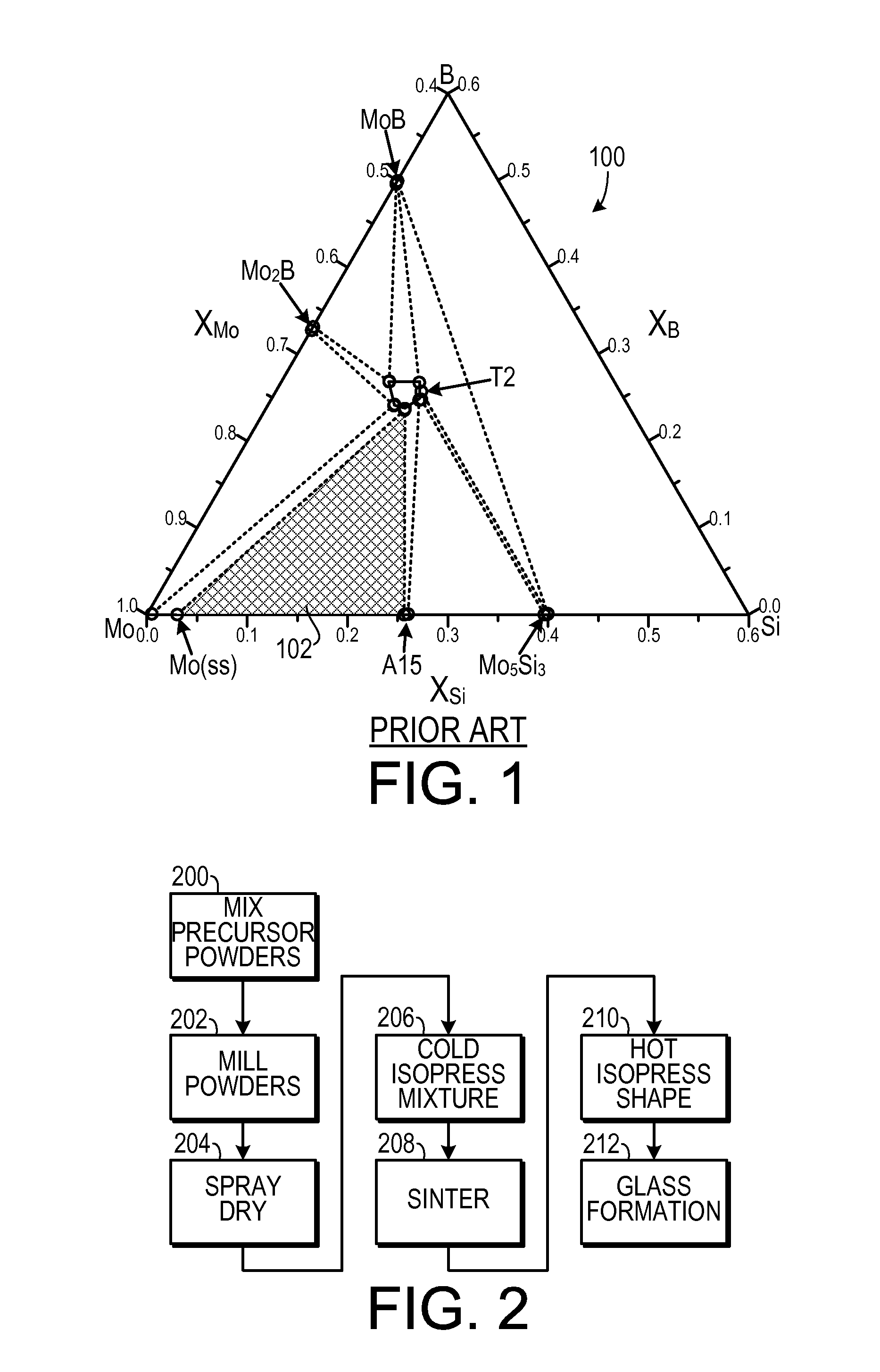
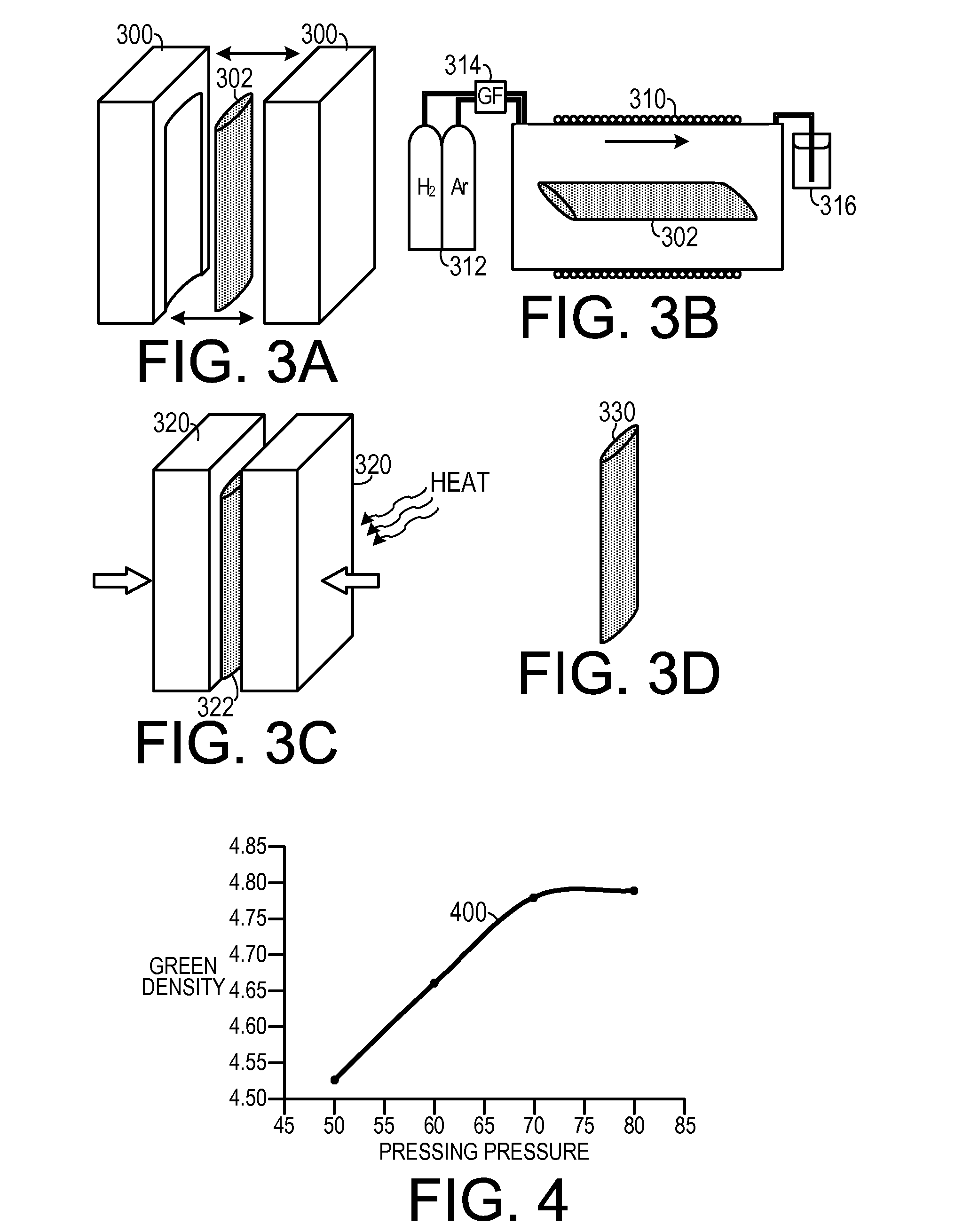
[0025]As shown in FIG. 2, one representative method of making a molybdenum, molybdenum silicide and molybdenum silicon boride composite material, includes mixing 200 a sub-micron boron nitride (such as BN) powder, a sub-micron silicon nitride (such as Si3N4) powder and a sub-micron molybdenum powder to form a composite precursor. The composite precursor may be milled 202 prior to the sintering action to break up agglomerates of the boron nitride powder, the silicon nitride powder and the molybdenum powder. The silicon nitride powder and the molybdenum po...


PUM

PropertyMeasurementUnit
Temperatureaaaaaaaaaa
Fractionaaaaaaaaaa
Percent by massaaaaaaaaaa

Abstract

In a method of making a molybdenum, molybdenum silicide and molybdenum silicon boride composite material, a boron nitride powder, a silicon nitride powder and a molybdenum powder are mixed to form a composite precursor. The composite precursor is sintered in an atmosphere consisting essentially of hydrogen and argon to form a sintered material. The sintered material is hot isostatic pressed to form the composite material into a final shape.

Description

CROSS-REFERENCE TO RELATED APPLICATION(S)[0001]This application claims the benefit of U.S. Provisional Patent Application Ser. No. 60 / 947,503, filed Jul. 2, 2007, the entirety of which is hereby incorporated herein by reference.STATEMENT OF GOVERNMENT INTEREST[0002]This invention was made with support from the U.S. government under grant number NAVAIR N00421-041-0002, awarded by the Office of Naval Research. The government may have certain rights in the invention.BACKGROUND OF THE INVENTION[0003]1. Field of the Invention[0004]The present invention relates to composite materials and, more specifically, to a composite material including molybdenum, molybdenum silicides and molybdenum silicon boride.[0005]2. Description of the Prior Art[0006]Nickel super alloy turbine blades in modern jet engines operate at temperatures approaching 1150° C. Using technologies such as thermal barrier coatings and elaborate cooling schemes, such engine temperatures may be pushed as high as 1500° C. Drama...

Claims


Application Information

Patent Timeline
IPC IPC(8): C22C32/00B22F3/15
CPCY10T428/12007C22C1/0491C22C1/045B22F2998/10B22F3/04B22F3/1007B22F2201/013B22F2201/10B22F3/24C22C1/047
Inventor COCHRAN, JOE K.LEE, KON J.MIDDLEMAS, MICHAEL R.
Owner GEORGIA TECH RES CORP
Learn More