Fuel Cell

a fuel cell and cell technology, applied in the field of fuel cells, can solve the problems of reducing electricity generation efficiency, difficult to obtain a sufficient output characteristic, and difficult to employ forced air cooling means, so as to improve fuel cell output and improve the ability to discharge heat from the air chamber. , the effect of reducing cross-over

Inactive Publication Date: 2009-01-08
BASF AG +1
View PDF3 Cites 2 Cited by
  • Summary
  • Abstract
  • Description
  • Claims
  • Application Information

AI Technical Summary

Benefits of technology

[0021]Furthermore, by connecting an outer surface part of the fuel electrode side casing and an outer surface part of the air electrode side casing to each other by means of a film having high thermal conductivity, it is possible to transfer heat discharged from the fuel cell main body to the air electrode side so as to collect the heat. As a result, an abnormal temperature rise of the anode side can be suppressed, the crossover is reduced, and the fuel cell output can be improved.
[0022]According to the fuel cell of the present invention, the capability of discharging heat from the air chamber is enhanced, whereby the temperature rise of the fuel cell is suppressed and, consequently, improvement in the output characteristics of the fuel cell and prolongation of the service life of the fuel cell are realized. Moreover, according to the fuel cell of the present invention, the temperature rise of the casing of the fuel cell and the exhausted air is suppressed, and it becomes therefore possible to apply the fuel cell to a mobile apparatus.

Problems solved by technology

There has been a problem with such a fuel cell using an aqueous solution of methanol as the fuel that it is difficult to obtain a sufficient output characteristic because of a difference between methanol and water in the vaporization rate.
When a fuel cell is used in a mobile apparatus, it is difficult to employ a forced air-cooling means such as a fan, and thus heat generated by the bonding of hydrogen and oxygen must be discharged to the outside of the fuel cell by natural air cooling.
If discharge of heat is insufficient and the temperature of the fuel cell becomes excessively high, electricity generation efficiency is lowered because of an increase in so-called crossover in which a liquid fuel such as methanol or the like passes from the fuel electrode to the air electrode, and further, the performance of the mobile apparatus main body is adversely affected or the portability of the mobile apparatus is impaired.

Method used


Image

  • Fuel Cell
  • Fuel Cell
  • Fuel Cell

Examples


Embodiment Construction

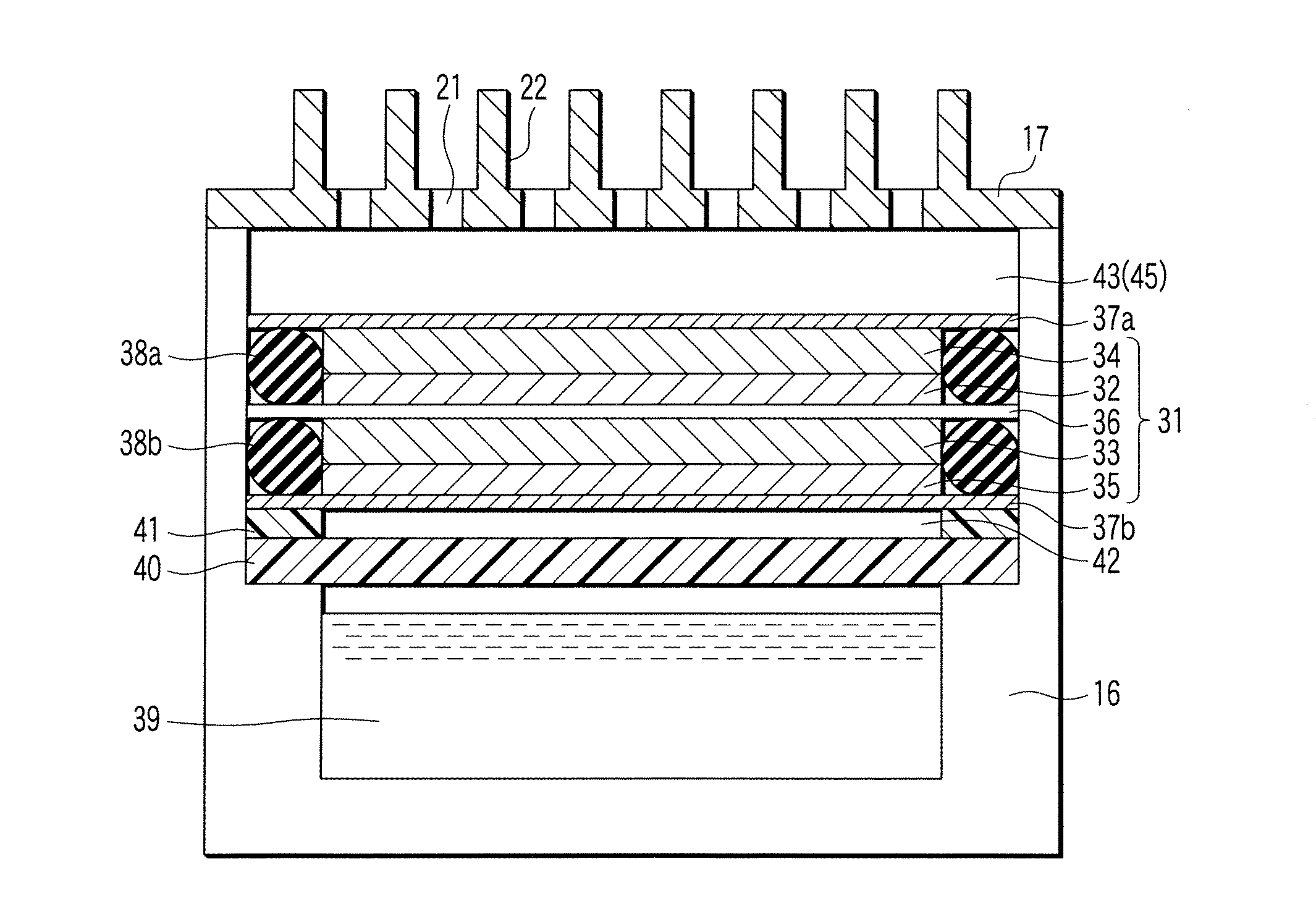
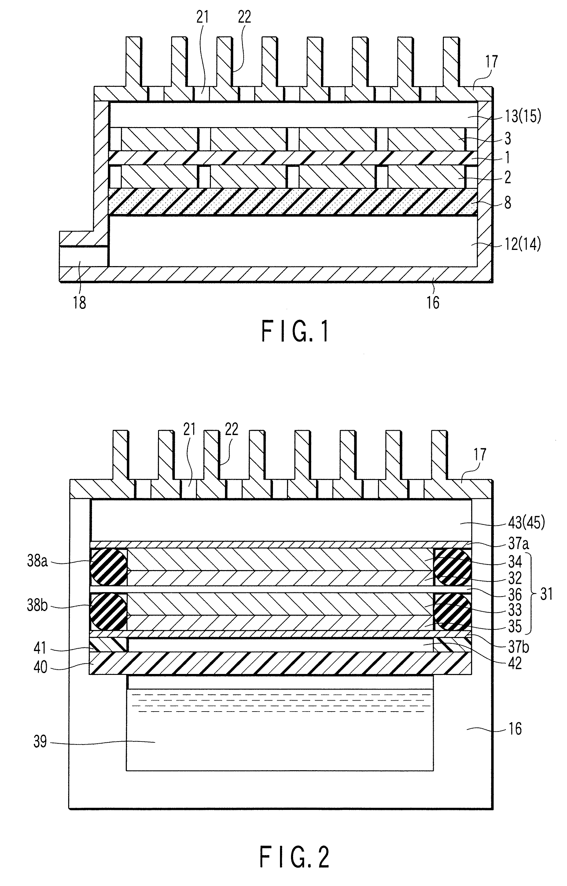
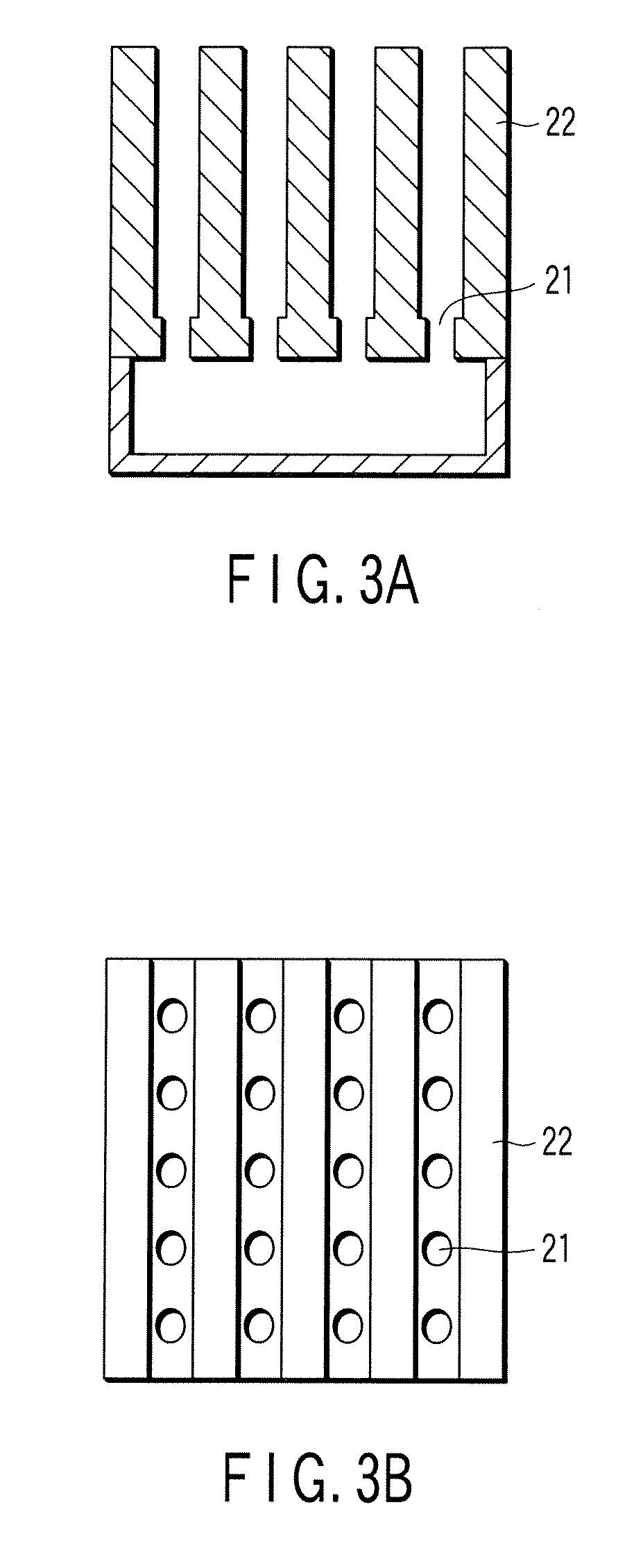
[0040]FIG. 1 shows an example (cross-sectional view) of a schematic configuration of a fuel cell according to the present invention. In FIG. 1, reference numeral 1 denotes a solid electrolyte membrane, 2 denotes a fuel electrode, 3 denotes an air electrode, 12 denotes a fuel tank, 13 denotes an air chamber, 16 denotes a casing of the fuel tank side, 17 denotes a casing of the air chamber side, 21 denotes an inlet port, and 22 denotes a fin.

[0041]A membrane electrode assembly (MEA) serving as a power generation section is constituted of a solid electrolyte membrane 1, and a fuel electrode 2 (anode) and an air electrode 3 (cathode) which are disposed on both sides of the solid electrolyte membrane 1. The fuel electrode 2 and the air electrode 3 are made of carbon paper coated with platinum / ruthenium alloy catalyst, and are joined to the solid electrolyte membrane 1 by thermo-compression bonding such that their surfaces coated with the catalyst are in contact with the membrane 1. In th...


PUM

PropertyMeasurementUnit
temperatureaaaaaaaaaa
thicknessaaaaaaaaaa
diameteraaaaaaaaaa

Abstract

A membrane electrode assembly is constituted of a solid electrolyte membrane 1 made of a polymeric material, and a fuel electrode 2 and an air electrode 3 which are disposed on both sides of the solid electrolyte membrane 1. A porous membrane 8 is attached to the back surface of the fuel electrode 2, and a fuel tank 12 is formed between a casing 16 of the fuel electrode 2 side and the porous membrane 8. The fuel tank 12 is filled with liquid-retaining sheets 14. An air chamber 13 is formed on the back surface of the air electrode 3, and the air chamber 13 is filled with moisture-retaining sheets 15. A casing 17 of the air electrode 3 side is provided with a number of inlet ports 21. Further, fins 22 are formed on an outer surface of the casing 17 of the air electrode side.

Description

TECHNICAL FIELD[0001]The present invention relates to a fuel cell in which hydrogen ions separated from a liquid fuel by using a catalyst at the fuel electrode are used to generate electricity and, more particularly, to a fuel cell in which an active transfer means such as a pump is not used to supply the liquid fuel to the fuel electrode.BACKGROUND ART[0002]In recent years, with the object of enabling various portable electronic apparatuses such as a notebook computer and a cellular phone to be used for a long time without charging, attempts to use fuel cells as power sources of these portable apparatuses are made at various places. The fuel cell has a feature that electricity is generated by supplying only a fuel and air, and when only the fuel is resupplied, electricity can be continuously generated for a long time. Accordingly, if downsizing is realized, the fuel cell can be regarded as a system which is very profitable as a power source of a portable apparatus.[0003]Particularl...

Claims


Application Information

Patent Timeline
Patent Type & Authority Applications(United States)
IPC IPC(8): H01M8/10H01M8/04H01M4/00
CPCH01M8/04007H01M8/04067H01M8/04201Y02E60/50H01M2008/1095Y02E60/523H01M8/1011H01M4/86H01M8/02H01M8/04
Inventor YOSHIDA, YUICHI
Owner BASF AG
Why Eureka
Try Eureka