Integrated wind-power electrical generation and compressed air energy storage system

a technology of integrated wind power and energy storage system, which is applied in the direction of electric generator control, machine/engine, greenhouse gas reduction, etc., can solve the problems of wind power suffering from a major negative, excessively the construction of large and expensive facilities, so as to prevent over-pressurization of storage units and maintain the required frequency stability

Inactive Publication Date: 2009-01-22
STULL MARK A +1
View PDF18 Cites 127 Cited by
  • Summary
  • Abstract
  • Description
  • Claims
  • Application Information

AI Technical Summary

Benefits of technology

[0015]An integrated wind power generation and storage system according to the present invention includes (i) a windmill having tower-mounted vanes that rotate when the wind blows, turning a rotatable shaft; (ii) an optional transmission system of one or more gears and clutches that can be used to control the rate at which power is transmitted to (iii) a rotating or piston-driven air compressor or pump located in the nacelle of the windmill or elsewhere; (iv) a feed system by which compressed air or a pumped, pressurized fluid is conducted to and injected into a storage unit at the desired pressure, typically by means of a feed with an adjustable valve or nozzle; (v) a storage unit in which energy storage is accomplished by expanding the volume of compressed air or pressurized fluid at constant or nearly constant pressure against a generated force that may be created by any means, which means may be the weight of a solid or liquid, a spring or other mechanical means, or an electromagnetic means; (vi) a containment mechanism that prevents the compressed air or pressurized fluid from escaping while the storage unit is partially or totally expanded; (vii) a feed system that conducts compressed air or pressurized fluid from the storage unit to a device that generates rotational motion and injects it into that device at the desired pressure, typically by means of a feed with an adjustable valve or nozzle; (viii) a device for generating rotational motion to rotate the armature of a electrical generator, which device may be one or more air motors, hydraulic motors, or high or low pressure turbines; (ix) an electrical generator which may be either a direct-current generator or an alternating current generator; and (x) one or more governors and other controls that can regulate air or fluid pressure throughout the system, prevent over-pressurization of the storage unit, and match the instantaneous energy input to the electrical generator to the instantaneous electrical load, maintaining required frequency stability.

Problems solved by technology

Unfortunately, wind power suffers from a major negative: the wind is a highly variable energy source that cannot be relied upon to produce power at times of high demand, and, perversely, may produce excess power at times of low demand.
Large-scale reliance on wind energy may create stability problems for the power grid.
The need to meet peak loads during light winds can require the construction of excessively large and expensive facilities.
And the unreliability of the wind makes wind power unsuitable for stand-alone generation without a back-up power source.
But this, too, poses problems.
Electricity is both difficult and expensive to store.
Probably the most common means of storing electrical energy, the lead acid battery, can cost up to several hundred dollars per kilowatt-hour and can create environmental hazards.
Therefore modern windfarms do not generally utilize energy storage systems.
A CAES system eliminates the need to burn this fuel by supplying the compressed air; however, it does not save energy, because energy is still required to compress the air.
CAES also has suffered from deficiencies that have prevented its widespread use.
One deficiency that has plagued CAES is the need for large containment facilities to store the required volume of pressurized air.
Thus large-scale storage requires large volumes, high pressures, or both.
But pressure vessels strong enough to contain a large volume of highly pressurized gas are prohibitively expensive on a per kilowatt-hour basis.
Although this avoids the cost of large containment vessels, it severely limits the locations at which CAES facilities can be built.
Another deficiency from which CAES suffers is inefficiency.
Energy losses in a CAES system can be substantial and can far exceed the losses typical of other types of energy storage.
As can be seen, this energy loss can drastically reduce the efficiency of a CAES system.
Nevertheless, deficiencies remain.
The requirement for underwater storage locations still restricts the location of the storage facility to places where water of the desired depth is present.
Although this would seem not to be a problem for offshore windfarms, other problems arise.
If storage bladders are located at shallow depths, large storage volumes are required, and this need cannot be avoided by the use of many small bladders because materials costs depend on surface area, which increases as the square of the linear dimension, while storage volume increases as the cube of the linear dimension.
Thus the materials cost of storage bladders per kilowatt-hour is lower for large bladders than for small ones, but large bladders may require higher fabrication costs and may also be more vulnerable to damage.
Tethering at great depths is likely to be expensive, especially for large bladders, perhaps prohibitively so.
Anchoring, on the other hand, may require a massive anchor.
Use of a material for the anchor much denser than water, such as iron or lead, can reduce the required mass and volume of the anchor; however, the cost of the material required could prove prohibitive.

Method used


Image

  • Integrated wind-power electrical generation and compressed air energy storage system
  • Integrated wind-power electrical generation and compressed air energy storage system
  • Integrated wind-power electrical generation and compressed air energy storage system

Examples


Embodiment Construction

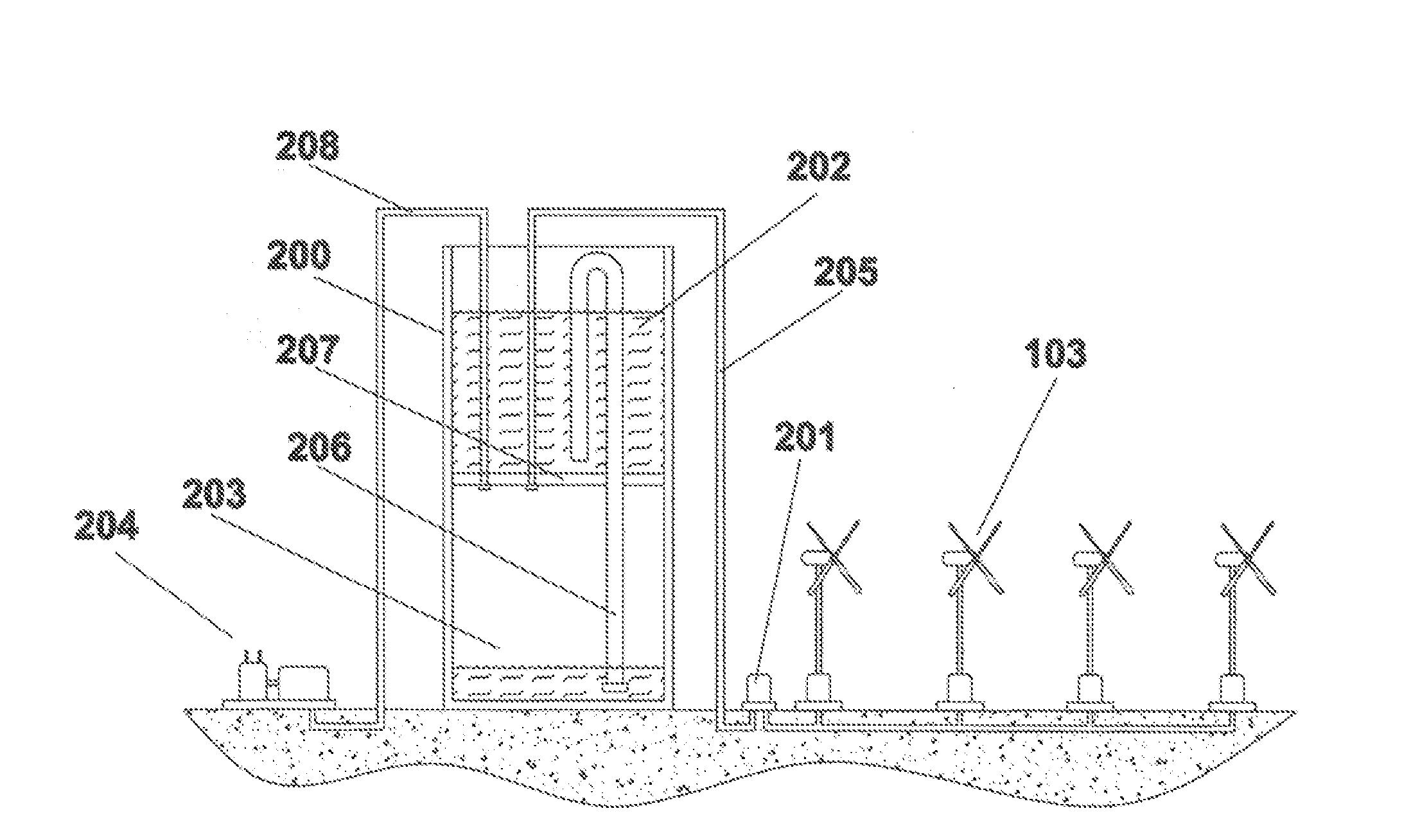
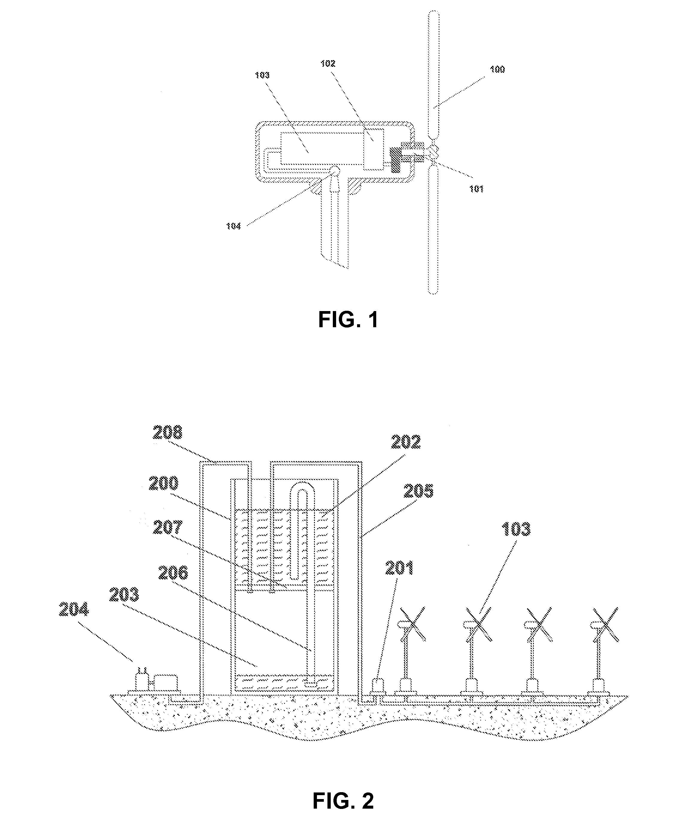
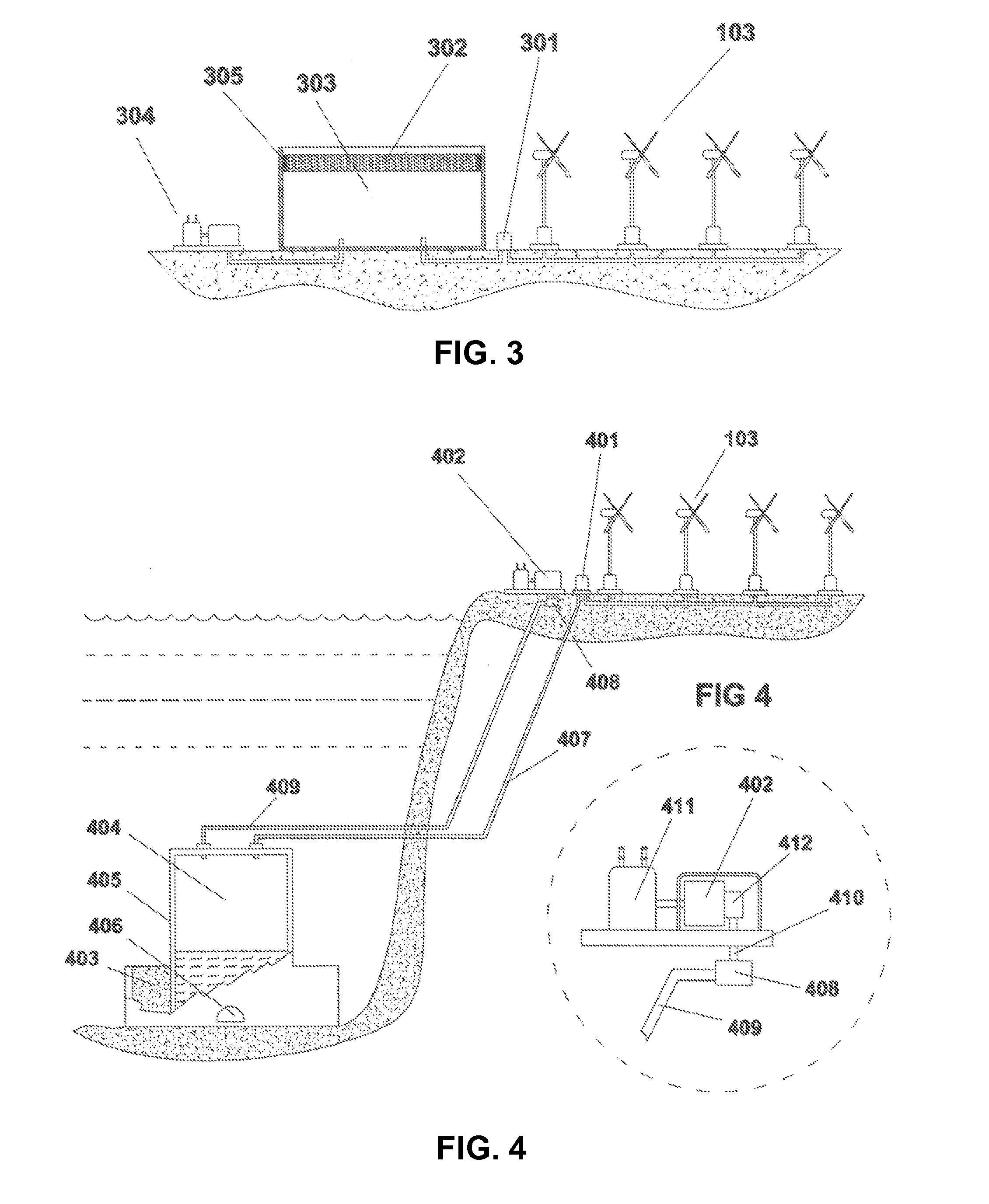
[0041]An integrated wind power generation and CAES storage system according to the present invention will now be described in detail with reference to FIGS. 1 through 5 of the accompanying drawings.

[0042]The invention comprises several methods and apparatuses which include one or more wind-powered air compressors or pumps, and one or more storage units for storing the compressed or pressurized air or other fluid medium. The volume of the storage unit is expanded at constant or nearly constant pressure by the compressed air or pressurized fluid inflow. Compressed air / pressurized fluid feeds with control valves feed compressed air or pressurized fluid from the wind-powered compressors or pumps to the storage units. The system includes a means for generating electricity by withdrawing compressed air or pressurized fluid from the storage units, which means may include one or more air turbines, hydraulic turbines and generators, as well as valves and feeds, and one or more governors whic...


PUM


Abstract

The present invention relates to a method and apparatus for using wind energy to compress air or pressurize a fluid as a means of storing energy. Compressed air or pressurized fluid is generated directly by the wind turbines, thereby avoiding the energy losses that occur when wind power is used first to generate electricity to run an electrically powered air compressor. The compressed air or pressurized fluid is stored by means of expanding a volume at constant or nearly constant pressure. This method avoids energy losses that would otherwise result from compressional heating; while also allowing lower pressures to be employed, reducing the cost of the containment facility and avoiding the need to locate facilities in geographically favored locations where underground storage is available. The invention permits both large and small-scale storage at low cost per unit of energy stored, thereby avoiding the difficulty of using a highly variable and unreliable source of energy such as the wind for electrical power generation. The invention can be used for generation and storage on land, in shallow near-shore waters and in deep-water locations far from shore.

Description

FIELD OF THE INVENTION[0001]The present invention relates to a method and apparatus for using wind energy to compress or pressurize air or other fluid medium as a means of storing energy and more particularly, to a system and method wherein the compressed air or pressurized fluid is stored by means of expanding a volume at a constant or nearly constant pressure generated by an applied force. This invention relates to an integrated system for harvesting and storing the kinetic energy of the wind and converting it to electrical power on an as-needed basis. The invention can also be used to provide a means for compressing air using wind energy.BACKGROUND OF THE INVENTION[0002]Wind energy is becoming increasingly important as a source of electrical power. Wind power does not entail the use of fossil fuels; therefore it both promotes energy independence and is non-polluting; in particular, it avoids greenhouse gas emissions. Furthermore, the cost of wind energy technology has declined, m...

Claims


Application Information

Patent Timeline
Patent Type & Authority Applications(United States)
IPC IPC(8): F03D9/02
CPCF03D9/028Y02E60/15Y02E10/725F03D9/17Y02E10/72Y02E60/16Y02E70/30F03D9/25F03D9/28
Inventor STULL, MARK A.MUCKLE, THOMAS A.
Owner STULL MARK A
Why Eureka
Try Eureka