
Integrated CMOS dc-dc converter implementation in low-voltage CMOS technology using ldo regulator

Inactive Publication Date: 2009-01-22
ATMEL CORP
View PDF9 Cites 25 Cited by
  • Summary
  • Abstract
  • Description
  • Claims
  • Application Information

AI Technical Summary

Benefits of technology

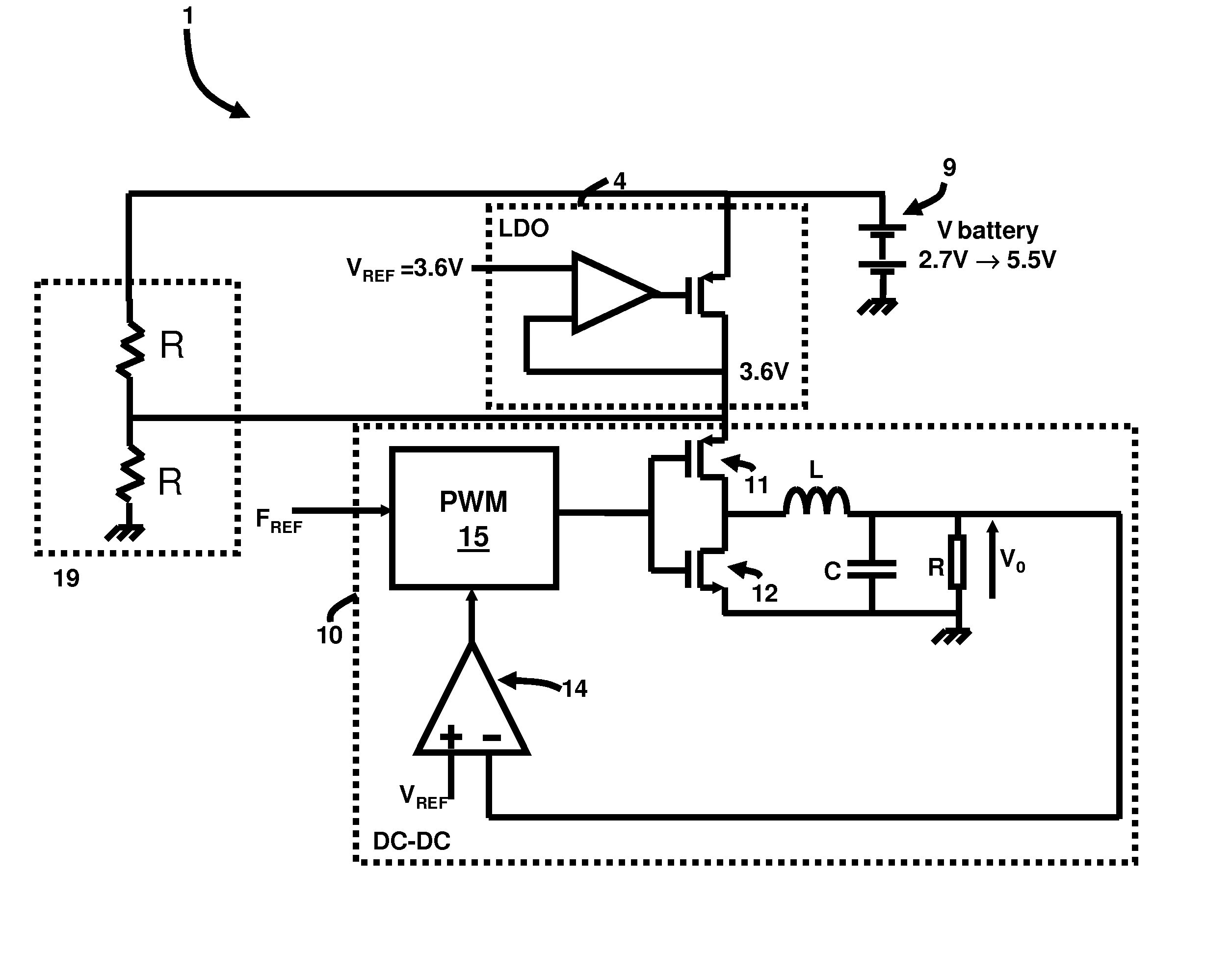
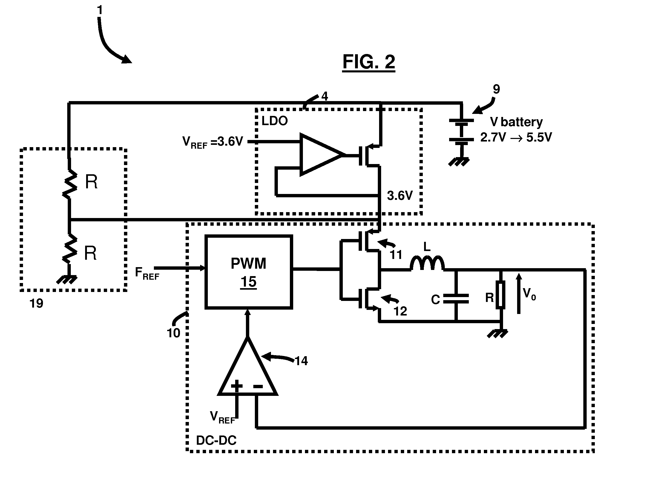
[0007]Another embodiment provides a communications system comprising an alternating (AC) source; a battery charger; and a cellular telephone comprising a battery adapted to produce a battery voltage; and a single system on-chip (SoC) integrated circuit chip comprising a LDO regulator operatively connected to the battery and adapted to provide a constant supply voltage from the battery voltage; and a DC-DC converter operatively connected to the LDO regulator, wherein the DC-DC converter is adapted to step down the constant supply voltage to a lower voltage level with high efficiency. Moreover, the constant supply voltage equals 3.6V at an output of the LDO, and wherein the constant supply voltage is applied to an input of the DC-DC converter. Also, the battery voltage equals at most 5.5V when the battery charger is plugged into the AC source. Preferably, the DC-DC converter comprises a pair of CMOS switches and a PWM adapted to provide pulse signals to drive the CMOS switches.

Problems solved by technology

The scaling breakdown voltage makes the circuit design challenging especially in portable applications such as cell phones where battery voltage does not scale down.
Moreover, it is difficult to design the integrated CMOS DC-DC converter that operates from this high input voltage.
The size and cost of such a solution tends to be relatively high.
However, SIP solutions tend to have a large size, and high cost (due to packaging complexity in SIP), and low yield.
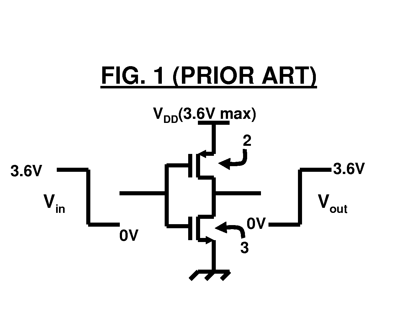
Therefore, using a single NMOS and PMOS switch is not possible for the 3.6V level in this technology that has devices rated at much lower operating voltages.

Method used


Image

  • Integrated CMOS dc-dc converter implementation in low-voltage CMOS technology using ldo regulator
  • Integrated CMOS dc-dc converter implementation in low-voltage CMOS technology using ldo regulator
  • Integrated CMOS dc-dc converter implementation in low-voltage CMOS technology using ldo regulator

Examples


Embodiment Construction

[0016]The embodiments herein and the various features and advantageous details thereof are explained more fully with reference to the non-limiting embodiments that are illustrated in the accompanying drawings and detailed in the following description. Descriptions of well-known components and processing techniques are omitted so as to not unnecessarily obscure the embodiments herein. The examples used herein are intended merely to facilitate an understanding of ways in which the embodiments herein may be practiced and to further enable those of skill in the art to practice the embodiments herein. Accordingly, the examples should not be construed as limiting the scope of the embodiments herein.

[0017]As mentioned, there remains a need for a converter capable of properly regulating battery voltage levels in a cellular telephone. The embodiments herein achieve this by providing a new technique to implement a DC-DC converter in low-voltage CMOS technology. Referring now to the drawings, ...


PUM


Abstract

An electrical circuit and method of power management of a cellular telephone includes a battery adapted to produce a battery voltage; a LDO regulator operatively connected to the battery and adapted to provide a constant supply voltage from the battery voltage; and a DC-DC converter operatively connected to the LDO regulator, wherein the DC-DC converter is adapted to step down the constant supply voltage to a lower voltage level, wherein the LDO regulator and the DC-DC converter are embedded on a single integrated circuit chip. The constant supply voltage equals 3.6V at an output of the LDO, and the constant supply voltage is applied to an input of the DC-DC converter. Moreover, the battery voltage equals at most 5.5V.

Description

BACKGROUND[0001]1. Technical Field[0002]The embodiments herein generally relate to complementary metal oxide semiconductor integrated circuit (CMOS IC) technologies, and, more particularly, to power management systems used in CMOS IC technologies.[0003]2. Description of the Related Art[0004]In modern CMOS IC technologies, as MOS transistor oxide thickness scales down, the breakdown voltage becomes lower. The scaling breakdown voltage makes the circuit design challenging especially in portable applications such as cell phones where battery voltage does not scale down. Voltage regulators are used to regulate the battery voltage down to a level which is suitable for the CMOS technology used. DC-DC converters are typically used because of their good efficiency versus low dropout (LDO) regulators. In cell phone applications, the battery voltage is normally 3.6V. With a careful design, it is possible to implement an integrated CMOS DC-DC converter with 3.6V input in 0.13 um CMOS technolog...

Claims


Application Information

Patent Timeline
IPC IPC(8): G05F1/563
CPCH02M3/156H02M2001/007H02M2001/0045H02M1/0045H02M1/007
Inventor CARR, FRANKEMIRA, AHMED A.ELWAN, HASSAN
Owner ATMEL CORP
Learn More