
Electronic part mounting structure and its manufacturing method

a technology for mounting structures and electronic parts, applied in the direction of dielectric characteristics, lithography/patterning, printed circuit non-printed electric components association, etc., can solve the problems of increasing the number of external connection terminals of semiconductor chips, increasing the number of external connection terminals to be modified for a smaller pitch, and affecting the quality of the printed circuit, etc., to achieve the effect of simplifying the mounting step

Active Publication Date: 2009-01-29
PANASONIC CORP
View PDF6 Cites 23 Cited by
  • Summary
  • Abstract
  • Description
  • Claims
  • Application Information

AI Technical Summary

Benefits of technology

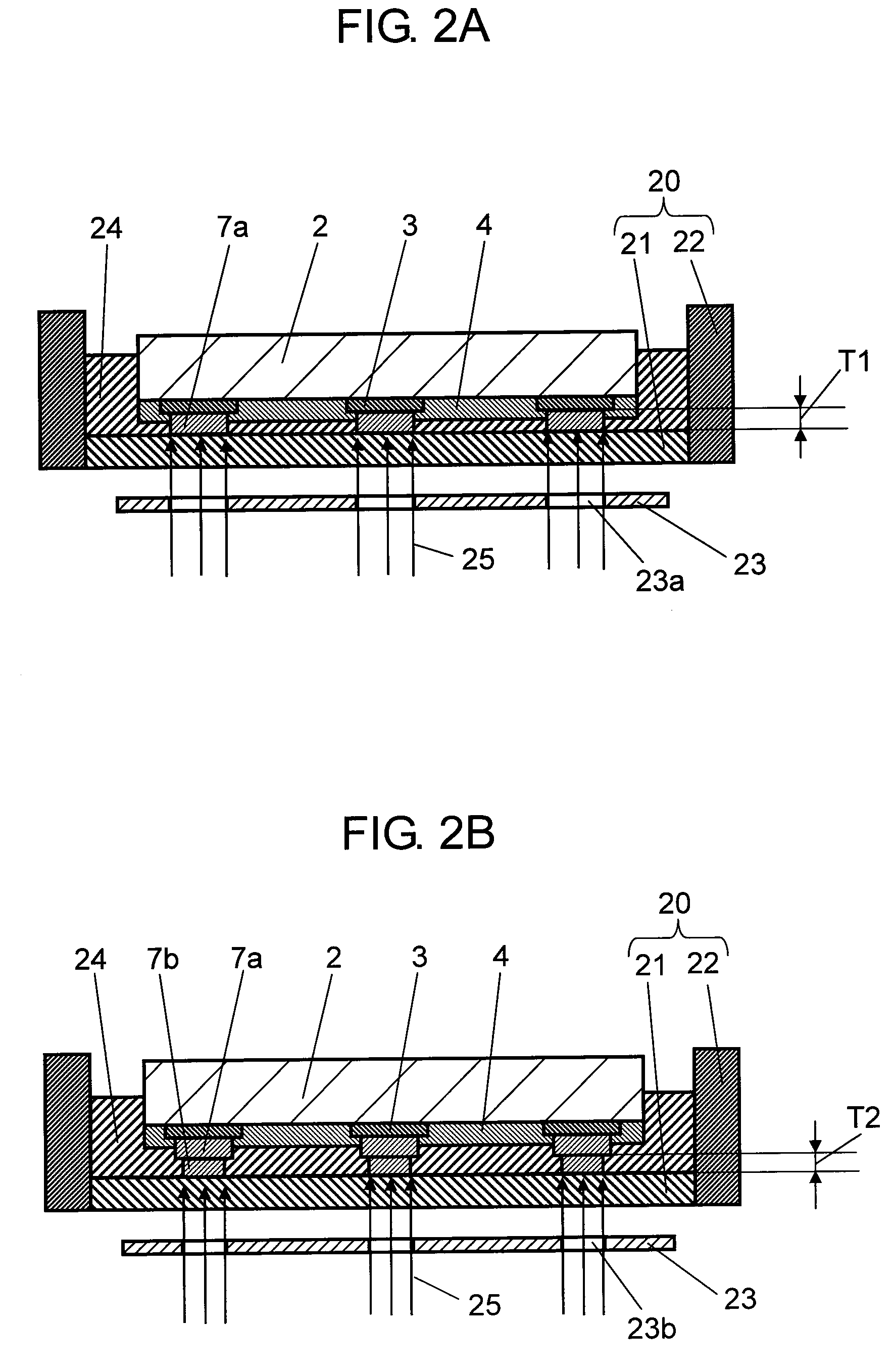
[0017]In this configuration, the protruding electrode made of a conductive resin can be formed collectively. Here, a liquid resin including the photosensitive resin is used, and thus, the liquid resin is selectively exposed using a photo mask where a plurality of liquid crystal cells are two-dimensionally aligned to be cured, so that the protruding electrode made of a conductive resin can be easily formed.
[0019]In accordance with this method, an electronic part mounting structure where connection is made using the protruding electrode made of a conductive resin can be easily fabricated.
[0021]In accordance with this method, an electronic part can be mounted on a substrate made of a transparent base simply through irradiation with light, and therefore, the mounting step can be simplified.

Problems solved by technology

Along with this miniaturization, the number of external connection terminals of semiconductor chips has increased, and the need for external connection terminals to be modified for a smaller pitch has become urgent.
However, thin semiconductor chips having a low dielectric material are generally fragile, and become cracked or damaged due to the load at the time of mounting.
Furthermore, the crystal lattice in semiconductor chips becomes distorted due to heat and the like, so that the transistor properties and the like tend to fluctuate in a case of use in such a state that there remains stress at the time of mounting.
In accordance with this method, however, though the inconsistency in the height of the protruding electrodes can be controlled, the height of the surface or the like of the protruding electrodes formed on the semiconductor element does not become constant in a case where there is a warp in the semiconductor element or the surface of the semiconductor element on which the protruding electrodes are formed is uneven.
That is to say, the inconsistency in height between the rear surface of the semiconductor element and the peaks of the protruding electrodes cannot be reduced, and as a result, there is a problem, such that defects in mounting cannot be reduced.
As the same as that in the above Patent Document 1, however, the height of the surface of the protruding electrodes formed on the surface of the semiconductor element does not become constant, and therefore, the inconsistency in the height between the rear surface of the semiconductor element and the peaks of the protruding electrodes cannot be reduced, and thus, there is the same problem as in Patent Document 1.

Method used


Image

  • Electronic part mounting structure and its manufacturing method
  • Electronic part mounting structure and its manufacturing method
  • Electronic part mounting structure and its manufacturing method

Examples


first exemplary embodiment

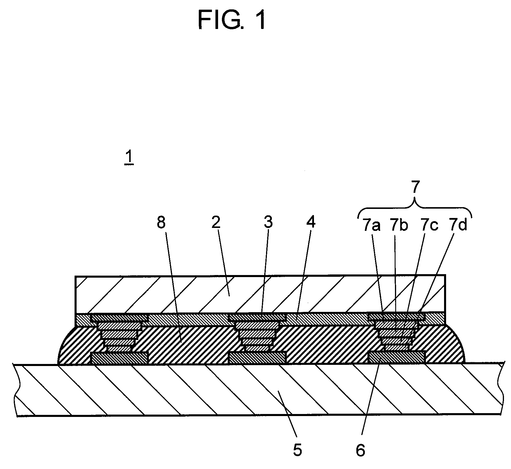
[0084]FIG. 1 is a cross sectional diagram showing the configuration of electronic part mounting structure 1 according to the first exemplary embodiment of the present invention. As shown in FIG. 1, electronic part mounting structure 1 is provided with electronic part 2 having a plurality of electrode terminals 3, substrate 5 where connection terminals 6 are provided in locations corresponding to electrode terminals 3, and protruding electrodes 7 which connect electrode terminals 3 and connection terminals 6. In addition, protruding electrodes 7 are formed of a conductive resin including a photosensitive resin and a conductive filler. Here, the photosensitive resin is sensitive to ultraviolet rays and visible light, and concretely, the peak sensitivity is to light having a wavelength of 500 nm or less. Hereinafter, visible light is taken as an example. At this time, protruding electrodes 7 have the modulus of elasticity of 5 to 30 in accordance with the dynamic hardness, and are suff...

second exemplary embodiment

[0145]FIG. 5 is a cross sectional diagram showing the configuration of electronic part mounting structure 30 according to the second exemplary embodiment of the present invention. As shown in FIG. 5, electronic part mounting structure 30 according to the present exemplary embodiment is different from the first exemplary embodiment in that the thickness of the first layer which makes contact with electrode terminals 33 among a plurality of layers that form protruding electrodes 37 is different depending on the location where electrode terminals 33 are placed. The another configuration is the same as in the electronic part mounting structure according to the first exemplary embodiment, and therefore, description thereof is not given in some cases.

[0146]That is to say, as shown in FIG. 5, electronic part mounting structure 30 is provided with electronic part 32 having a plurality of electrode terminals 33, substrate 35 provided with connection terminals 36 in locations corresponding to...

third exemplary embodiment

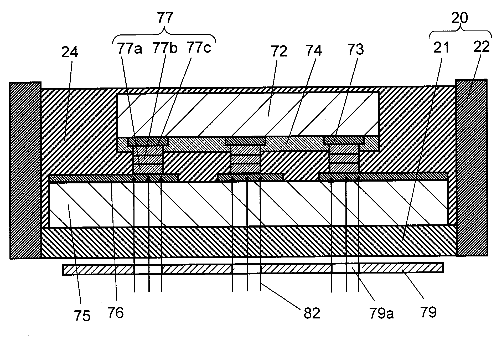
[0180]FIG. 9 is a cross sectional diagram showing the configuration of electronic part mounting structure 70 according to the third exemplary embodiment of the present invention. As shown in FIG. 9, electronic part mounting structure 70 is provided with electronic part 72 having a plurality of electrode terminals 73, substrate 75 provided with connection terminals 76 in locations corresponding to electrode terminals 73, and protruding electrodes 77 for connecting electrode terminals 73 and connection terminals 76. In addition, protruding electrodes 77 are formed of a conductive resin including a photosensitive resin which is sensitive to visible light and a conductive filler. Here, the material for forming the conductive resin and the properties thereof are the same as in the first exemplary embodiment, and therefore, descriptions thereof are not given.

[0181]In addition, in the present exemplary embodiment, protruding electrodes 77 are approximately in columnar form and are not subs...


PUM

PropertyMeasurementUnit
Temperatureaaaaaaaaaa
Percent by massaaaaaaaaaa

Abstract

An electronic part mounting structure includes electronic part (2) having a plurality of electrode terminals (3), a substrate provided with connection terminals (6) in locations corresponding to these electrode terminals (3), and protruding electrode (7) for connecting one of electrode terminals (3) and one of connection terminals (6), where electrode terminal (3) of electronic part (2) and connection terminal (6) of substrate (5) are connected through protruding electrode (7), and protruding electrode (7) is formed of a conductive resin including a photosensitive resin and a conductive filler.

Description

TECHNICAL FIELD[0001]The present invention relates to an electronic part mounting structure where an electronic part, as typified by a semiconductor element, is mounted on a substrate or the like using a flip chip mounting, as well as its manufacturing method.BACKGROUND ART[0002]In recent years, wiring patterns have been miniaturized to, for example, 65 nm to 45 nm, on the basis of the miniaturization rule, in order to increase the storage density of semiconductor chips. Along with this miniaturization, the number of external connection terminals of semiconductor chips has increased, and the need for external connection terminals to be modified for a smaller pitch has become urgent. Meanwhile, external connection terminals have been formed in an area bump system, where the entire surface of the semiconductor chip on which the circuit is formed is used, in order to prevent the pitch of the external connection terminals from becoming too small, instead of in a conventional peripheral ...

Claims


Application Information

Patent Timeline
IPC IPC(8): H01L23/52H01L21/00
CPCH01L24/10H01L2224/1308H01L2224/13083H01L2224/13099H01L2224/1319H01L2224/16225H01L2224/32225H01L2224/48091H01L2224/48227H01L2224/48465H01L2224/73204H01L2224/73265H01L2924/01013H01L2924/01015H01L2924/01029H01L2924/01042H01L2924/01046H01L2924/01074H01L2924/01078H01L2924/01079H01L2924/01082H01L2924/09701H01L2924/3025H01L2924/3511H05K1/095H05K3/321H05K2201/0108H05K2201/10674H05K2201/10719H05K2203/0514H01L2924/00013H01L2924/01006H01L2924/01033H01L2924/01047H01L2924/014H01L2924/15311H01L2924/07811H01L2224/0401H01L2224/06102H01L2924/07802H01L24/13H01L2924/00014H01L2924/00H01L2924/00012H01L24/05H01L24/06H01L24/11H01L24/14H01L24/73H01L2224/05624H01L2224/05644H01L2224/11554H01L2224/13H01L2224/1403H01L2924/01005H01L2924/01016H01L2924/15787H01L2924/351H05K1/18H01L21/00
Inventor SAKURAI, DAISUKEYAGI, YOSHIHIKO
Owner PANASONIC CORP
Learn More