CID retention device for Li-ion cell

a technology of li-ion cells and retention devices, which is applied in the direction of batteries, cell components, sustainable manufacturing/processing, etc., can solve the problems of increased safety problems, low efficiency, and compromise of reliability and safety of such batteries, so as to improve capacity, reduce risk, and increase the effect of cell siz

Inactive Publication Date: 2009-01-29
BOSTON POWER INC
View PDF59 Cites 62 Cited by
  • Summary
  • Abstract
  • Description
  • Claims
  • Application Information

AI Technical Summary

Benefits of technology

[0015]The CIDs of the invention, by contrast, can provide a solution to such problems, because they cause batteries or battery packs, in which they are incorporated, to run at their full capacity with lower risk than typically exists in commercially available embodiments, since they interrupt current flow at relatively low temperatures during overcharge. Thus, the batteries and battery packs of the invention can employ relatively large cells, and provide improved capacity with greater safety by reducing likelihood of thermal runaway in the cells when they are exposed to abuse conditions, such as an overcharge.
[0016]In some embodiments of the invention, the low pressure CID is in electrical communication with the battery can. This design can provide improved battery safety particularly in a battery that does not use a crimped cap design. Batteries using crimped cap designs (e.g. steel can cylindrical 18650s found in the market today) often are affected by manufacturing and safety issues surrounding the can assembly and materials, including the facts that such cans use iron-containing materials that can corrode over time and that the crimping process is known to be a possible source of metal contamination in such cells. CID devices, used in such conventional batteries, are crimped into the battery can, and are electrically insulated from the battery can. While use of non-crimped battery designs are known, including use of prismatic Al cans, no CIDs have been developed for use in such cells unless incorporated by some means of crimping. Additionally, use of crimping methods to incorporate CIDs generally is not an efficient utilization of space, which is one of a key design consideration for batteries. In contrast, the present invention enables incorporation of the low pressure CID in a non-crimped battery can by means other than crimping, partly due to the fact ...

Problems solved by technology

Batteries that employ Li-ion cell chemistry may produce gas when they are improperly charged, shorted or exposed to high temperatures.
This gas can be combustible and may compromise the reliability and safety ...

Method used


Image

  • CID retention device for Li-ion cell
  • CID retention device for Li-ion cell
  • CID retention device for Li-ion cell

Examples


example 1

Preparation of the CIDs of the Invention

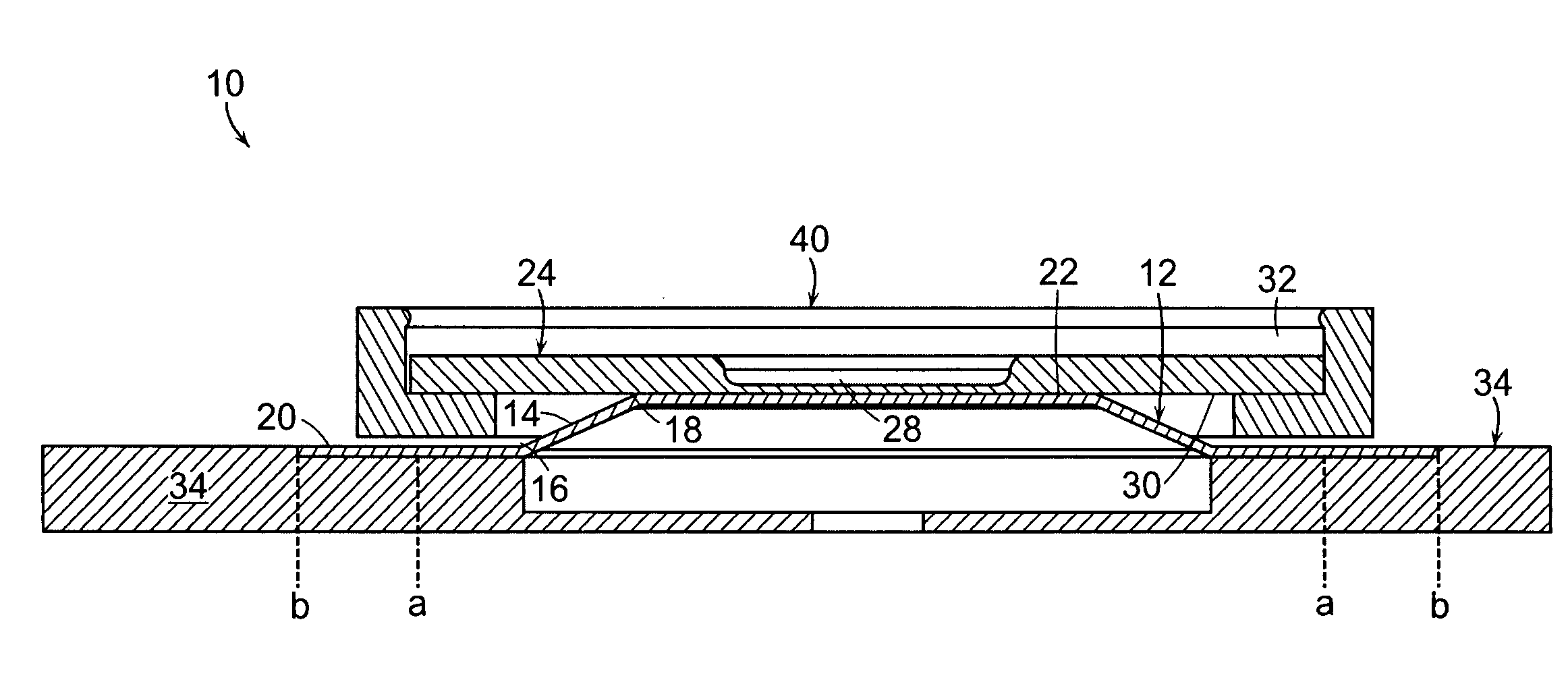
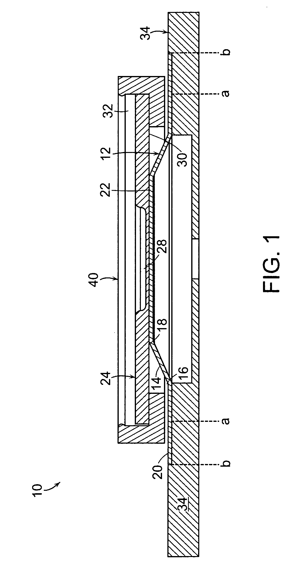
[0116]In this example, a process for manufacturing a CID as shown in FIG. 1, which includes a first conductive plate, a second conductive plate, a retainer between the two conductive plates, and an end plate.

[0117]1A. Preparation of First Conductive Plate 12

[0118]The first conductive plate (hereinafter “pressure disk”) was formed by stamping a flat sheet of Aluminum 3003 (HO) into a shape resembling a hat with angled edges, as shown in FIGS. 2A-2C. A flat aluminum sheet having a thickness of about 0.005 inches (about 0.127 mm) (“d” in FIG. 2C) was used. The flat aluminum sheet was first depressed using a conical punch with a flat top to thereby form a conical frustum, a base having a diameter of about 0.315 inches (about 8 mm) (“a” in FIG. 2C), and a flat top at a height of about 0.03 inches (about 0.762 mm) (“c” in FIG. 2C) from the base. The diameter of the flat top (“b” in FIG. 2C) was about 0.215 inches (about 5.46 mm). The angle of the fr...

example 2

Preparation of the Battery of the Invention

[0133]Lithium-ion batteries were prepared using either 100% of Li1+xCoO2 (x is about 0-0.2), or a mixture that includes about 80 wt % of Li1+xCoO2 (x is about 0-0.2) and about 20 wt % of Li1+x9Mn(2−y9)O4 (each of x9 and y9 is independently about 0.05-0.15) as their active cathode materials. The cell thickness, cell width and cell height of the batteries were about 18 mm, about 37 mm and about 65-66 mm, respectively. Anodes of the batteries were of carbon. About 5.5 wt % of biphenyl (BP) was included in the electrolytes of the batteries. Al tabs and Ni tabs were employed as the cathode and anode tabs of the batteries, respectively. The Al tabs of the cathode were welded onto the second conductive plate of the CID described above in Example 1. The Ni tabs of the anode of the battery were welded onto the feed-through device of the battery (see FIG. 8A and FIG. 8D).

example 3

CID Activation Tests

[0134]The CIDs prepared as described in Example 1, not installed in battery cells, were tested in this example. For these tests, a pressure test fixture was designed so that the CID side of the end plate (34) of the CIDs could be pressurized with compressed air or nitrogen to test the CID Release Pressure (CRP). The test pressure was started at about 5 bar (gauge), and increased in 0.5 bar increments. At each pressure setting, the end plate was kept under the test pressure for 10 seconds before the pressure increase. The pressure increase was done gradually between each setting so that the CRP could be observed with a resolution of a 0.1-0.2 bar. The test results are summarized in FIG. 10. As shown in FIG. 10, the average gauge pressure of the CID trip was about 7.7 bar.


PUM

PropertyMeasurementUnit
Thicknessaaaaaaaaaa
Thicknessaaaaaaaaaa
Thicknessaaaaaaaaaa

Abstract

A low pressure current interrupt device (CID) activates at a minimal threshold internal gauge pressure in a range of, for example, between about 4 kg/cm2 and about 9 kg/cm2. Preferably, the CID includes a first conductive plate and a second conductive plate in electrical communication with the first conductive plate, the electrical communication between the first and the second conductive plates being interrupted at the minimal threshold internal gauge pressure. More preferably, the first conductive plate includes a frustum having a first end and a second end, a base extending radially from a perimeter of the first end of the frustum, and an essentially planar cap sealing the second end of the frustum. The first end has a broader diameter than the second end. More preferably, the second conductive plate is in electrical contact with the essentially planar cap through a weld. A battery, preferably a lithium-ion battery, comprises a CID as described above. A method of manufacturing such a CID comprises forming first and second conductive plates as described above, and welding the second conductive plate onto the first conductive plate while a temperature of the first conductive plate is controlled so as not to exceed the melting point of a surface of the first conductive plate opposite the weld.

Description

RELATED APPLICATION[0001]This application claims the benefit of U.S. Provisional Application No. 60 / 936,825, filed Jun. 22, 2007. The entire teachings of the above application are incorporated herein by reference.BACKGROUND OF THE INVENTION[0002]Li-ion batteries in portable electronic devices typically undergo different charging, discharging and storage routines based on their use. Batteries that employ Li-ion cell chemistry may produce gas when they are improperly charged, shorted or exposed to high temperatures. This gas can be combustible and may compromise the reliability and safety of such batteries. A current interrupt device (CID) is typically employed to provide protection against any excessive internal pressure increase in a battery by interrupting the current path from the battery when pressure inside the battery is greater than a predetermined value. The CID typically includes first and second conductive plates in electrical communication with each other. The first and se...

Claims


Application Information

Patent Timeline
IPC IPC(8): H01M14/00H01M2/26H01M6/00H01M10/0525H01M10/36H01M50/103H01M50/107H01M50/541H01M50/574H01M50/586H01M50/593
CPCH01M2/0217H01M2/022H01M2/1235H01M2/34Y10T29/49108H01M10/0525H01M2002/0205Y02E60/122H01M2/345Y02E60/10H01M50/107H01M50/103H01M50/342H01M50/578Y02P70/50H01M50/593H01M50/586H01M50/574H01M10/425H01M4/525H01M4/505H01M4/364H01M4/131H01M2010/4271H01M2200/00
Inventor ONNERUD, PERPARTIN, PHILLIP E.CHAMBERLAIN, II, RICHARD V.LINNA, JAN-ROGER B.ELIA, MIMMO
Owner BOSTON POWER INC
Why Eureka
Try Eureka