Biochip reader and fluorometric imaging apparatus

a fluorometric imaging and biochip reader technology, applied in the field of biochip readers, can solve the problems of inconvenient operation, inconvenient use, and inconvenient use of the conventional apparatus as discussed abov

Inactive Publication Date: 2009-02-05
YOKOGAWA ELECTRIC CORP
View PDF5 Cites 7 Cited by
  • Summary
  • Abstract
  • Description
  • Claims
  • Application Information

AI Technical Summary

Benefits of technology

[0028]An object of the present invention is to solve the aforementioned problems by providing a fluorometric imaging apparatus that is simple in configuration and inexpensive, and permits easy positioning of specimens.
[0032]According to such an apparatus configuration as discussed above, excitation light from the light source is transformed into a multibeam by means of microlenses and multiple beams are simultaneously irradiated at the specimen through the zoom lens. Accordingly, there is no need to perform optical scanning as has been conventionally done, thus simplifying the apparatus configuration.
[0033]If a comparison is made with reference to the same readout time, excitation light used for the biochip reader of the present invention can be made weaker, in inverse proportion to the number of beams, than that used for optical scanning. Since there is no need for irradiating high-intensity laser light as has been conventionally done, the apparatus of the present invention avoids the risk of bleaching of fluorescent dyes. In addition, it is possible to measure even weak fluorescent light.
[0034]Furthermore, since the biochip reader of the present invention uses a zoom lens, it is possible to easily change the pitch between beams for irradiating specimens. This means that the biochip reader offers another advantage that even if sites of a specimen are arranged at an arbitrary pitch, it is possible to make the pitch between the sites of the specimen agree with the pitch between beams.
[0038]With such an apparatus configuration as described above, it is possible to position the specimen by skillfully utilizing excitation light that passes through the specimen or reflects off the surface thereof, and that has not been used conventionally.

Problems solved by technology

However, such a conventional apparatus as discussed above has had the following problems.
This method has the disadvantage that the mechanism for moving the stage is too complex and requires extra time before the image is obtained.
Another disadvantage is that the intensity of light beams must be high enough for the method to be effective.
Higher intensities of light may result in the problem, however, of bleaching of the fluorescent dyes of samples.
Yet another problem is that a spot of high-intensity light tends to saturate detector 9 or the A / D converter (not shown in the figure) subsequent to the detector and, therefore, the gain of the detector or converter must be lowered.
Lowering the gain would result in the disadvantage, however, that weak light cannot be measured and the dynamic range is narrowed.
In this application, however, it is not possible to observe the entire cell by means of fluorescence alone.
However, such a positioning mechanism as discussed above not only has poor maneuverability but tends to be large in scale and therefore expensive.
Another problem inherent with the mechanism is that it is troublesome to move the beam splitter out of or into the optical path.

Method used


Image

  • Biochip reader and fluorometric imaging apparatus
  • Biochip reader and fluorometric imaging apparatus
  • Biochip reader and fluorometric imaging apparatus

Examples


Embodiment Construction

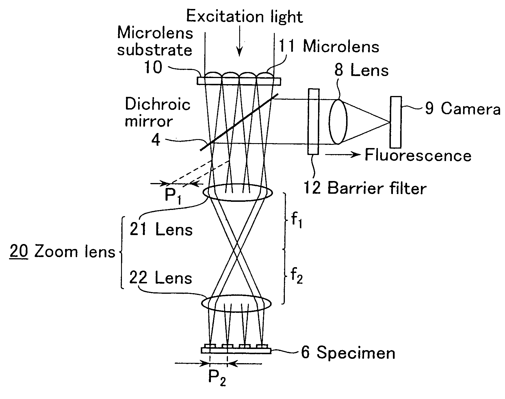
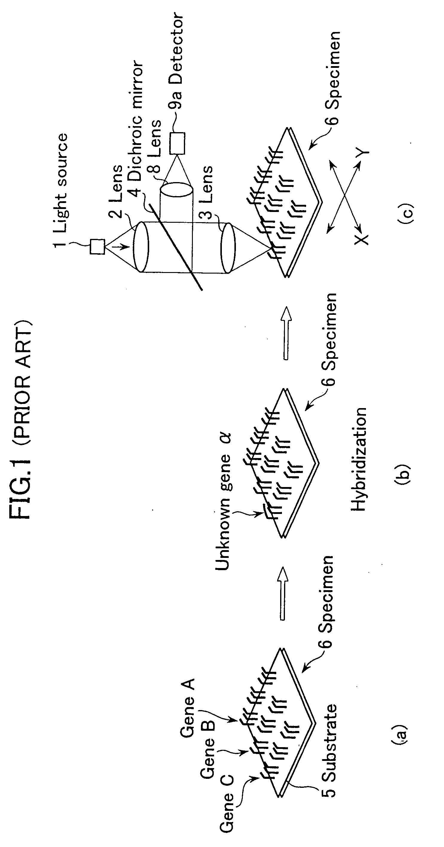
[0046]Now the present invention will be described in detail with reference to the accompanying drawings. FIG. 3 is a schematic view showing one embodiment of the biochip reader in accordance with the present invention. In the figure, elements identical to those shown in FIG. 1 are referenced alike and excluded from the description hereinafter presented.

[0047]In FIG. 3, numeral 10 denotes a microlens substrate, numeral 11 denotes a microlens, numeral 12 denotes a barrier filter, and numeral 20 denotes a telecentric zoom lens. On microlens substrate 10, a plurality of microlenses 11 are arranged at equal pitch P.sub.1.

[0048]Zoom lens 20 comprises lens 21 with focal length f.sub.1 and lens 21 with focal length f.sub.2, where both focal length f.sub.1 and focal length f.sub.2 are variable. Zoom lens 20 is located between dichroic mirror 4 and specimen 6.

[0049]Note that although each of lenses 21 and 22 is illustrated as a single lens for the sake of convenience, these lenses are usually...


PUM

PropertyMeasurementUnit
focal lengthaaaaaaaaaa
fluorescentaaaaaaaaaa
fluorometric imagingaaaaaaaaaa

Abstract

The present invention provides a biochip reader for reading the image information of samples using a photodetector device, by irradiating a corresponding beam of excitation light at each site of a biochip on which a plurality of the samples are arranged at equal pitches, the biochip reader comprising: a microlens substrate provided with a plurality of microlenses to transform excitation light to be irradiated at the biochip into a multibeam; and a zoom lens located between the microlens substrate and the biochip and capable of projecting the multibeam while adjusting the pitch between sites of the biochip to the pitch of the multibeam. The present invention further provides a fluorometric imaging apparatus for detecting the image of a specimen by irradiating excitation light at samples on the specimen arranged in a two-dimensional manner and measuring fluorescent light produced from a fluorescent substance attached to the specimen, the fluorometric imaging apparatus comprising: a two-dimensional photodetector device for detecting excitation light passing through the specimen or reflecting off the surface thereof; and movement means for repositioning the specimen according to images observed on the photoreceptor device.

Description

[0001]This application is a divisional application of U.S. Ser. No. 10 / 198,174, filed on Jul. 19, 2002, which claims priority of Japanese Patent Application Nos. 2001-241862 and 2001-241863, both filed on Aug. 9, 2001, which are hereby incorporated by reference in their entirety.BACKGROUND OF THE INVENTION[0002]1. Field of the Invention[0003]The present invention relates to a biochip reader for reading weak fluorescent light produced by exciting samples on a biochip with excitation light. More specifically, the present invention relates to improvements made to accelerate measurement, simplify the apparatus, reduce damage to samples, flatten the intensity distribution within the spot of light produced when a beam of excitation laser light is condensed with a microlens, and enable free definition of the pitch at which samples on a biochip are arranged.[0004]The present invention further relates to a fluorometric imaging apparatus for measuring biochips of DNA, RNA, protein, and the li...

Claims


Application Information

Patent Timeline
Patent Type & Authority Applications(United States)
IPC IPC(8): G01N21/64G02B21/00
CPCG01N21/6428G01N21/6452G01N21/6458G02B21/16G01N2021/6491G02B21/0044G02B21/0076G01N2021/6478
Inventor TANAAMI, TAKEO
Owner YOKOGAWA ELECTRIC CORP
Why Eureka
Try Eureka