Cellular composite grid-stiffened structure

a composite material and grid-stiffening technology, applied in the field of grid-stiffened structures, can solve the problems of unidirectional placement of grid stiffeners, structural limitation of transverse stiffener strength, and inability to propagate unimpeded through the structure, so as to achieve the effect of increasing the structural integrity of the cellular composite structur

Inactive Publication Date: 2009-02-12
THE BOEING CO
View PDF2 Cites 11 Cited by
  • Summary
  • Abstract
  • Description
  • Claims
  • Application Information

AI Technical Summary

Benefits of technology

[0009]Cellular composite structures according to the present invention provide several advantages. By providing separate cap members having multiple layers of material to create each of the associated riser walls bondable to individual intersecting ribs, structural integrity of the cellular composite structure is increased. When the cap members are thermally bonded to the intersecting ribs of the grid, a close dimensional fit of the cap members ensures that the flow of resin leaves few or no gaps where a crack can initiate and propagate from.

Problems solved by technology

Grid stiffeners commonly have unidirectional fiber placement.
Transverse stiffener strength is therefore a structural limitation.
Further, if disbonding occurs anywhere in the stiffener / skin bond line, the disbanding can propagate throughout the structure unimpeded.
The bond between the stiffeners and the body skin is not maximized because of the lack of interweaving between the skin and the parallel positioned stiffener fibers.

Method used


Image

  • Cellular composite grid-stiffened structure
  • Cellular composite grid-stiffened structure
  • Cellular composite grid-stiffened structure

Examples


Embodiment Construction

[0023]The following description of the preferred embodiments is merely exemplary in nature and is in no way intended to limit the invention, its application, or uses.

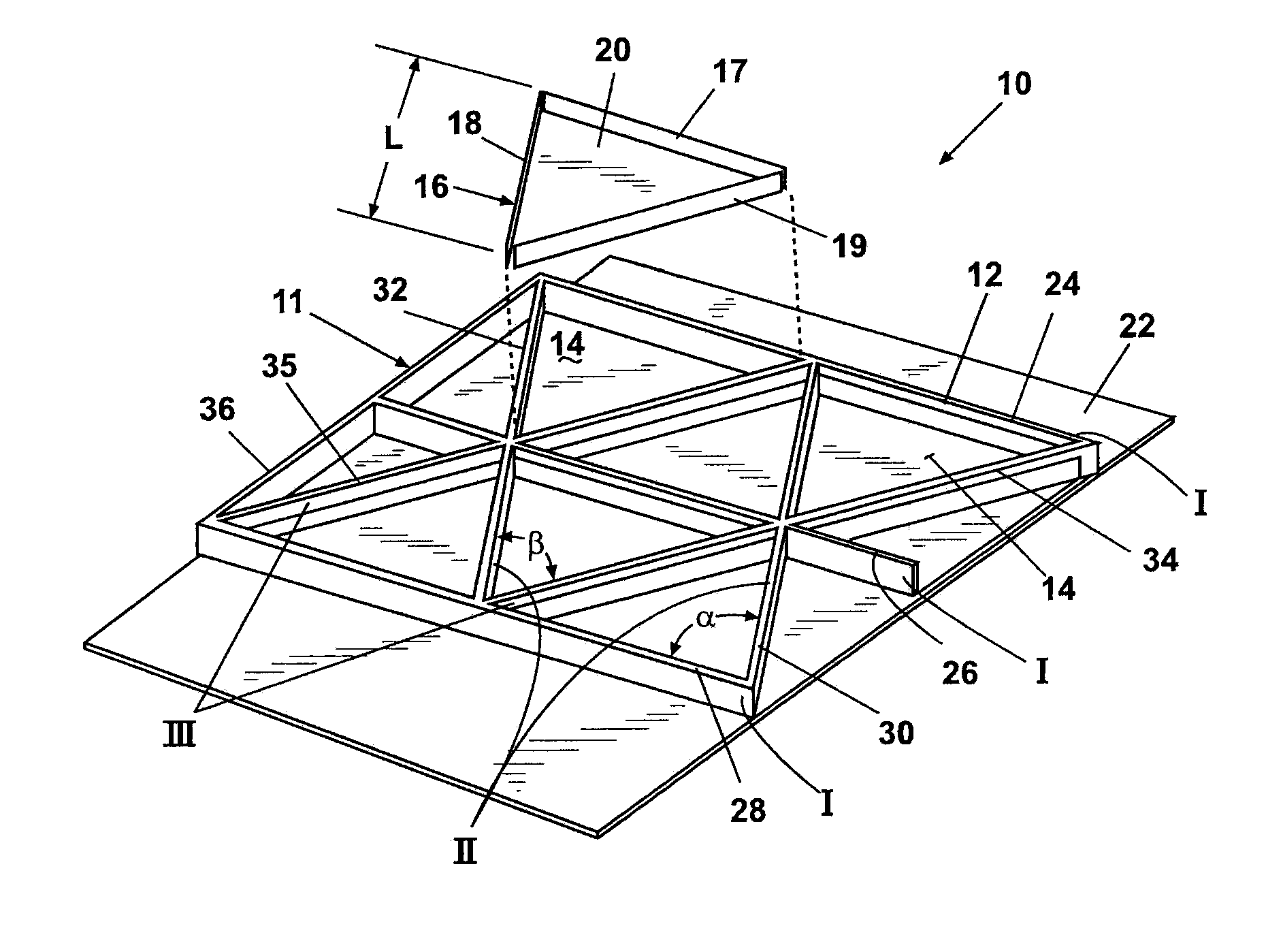
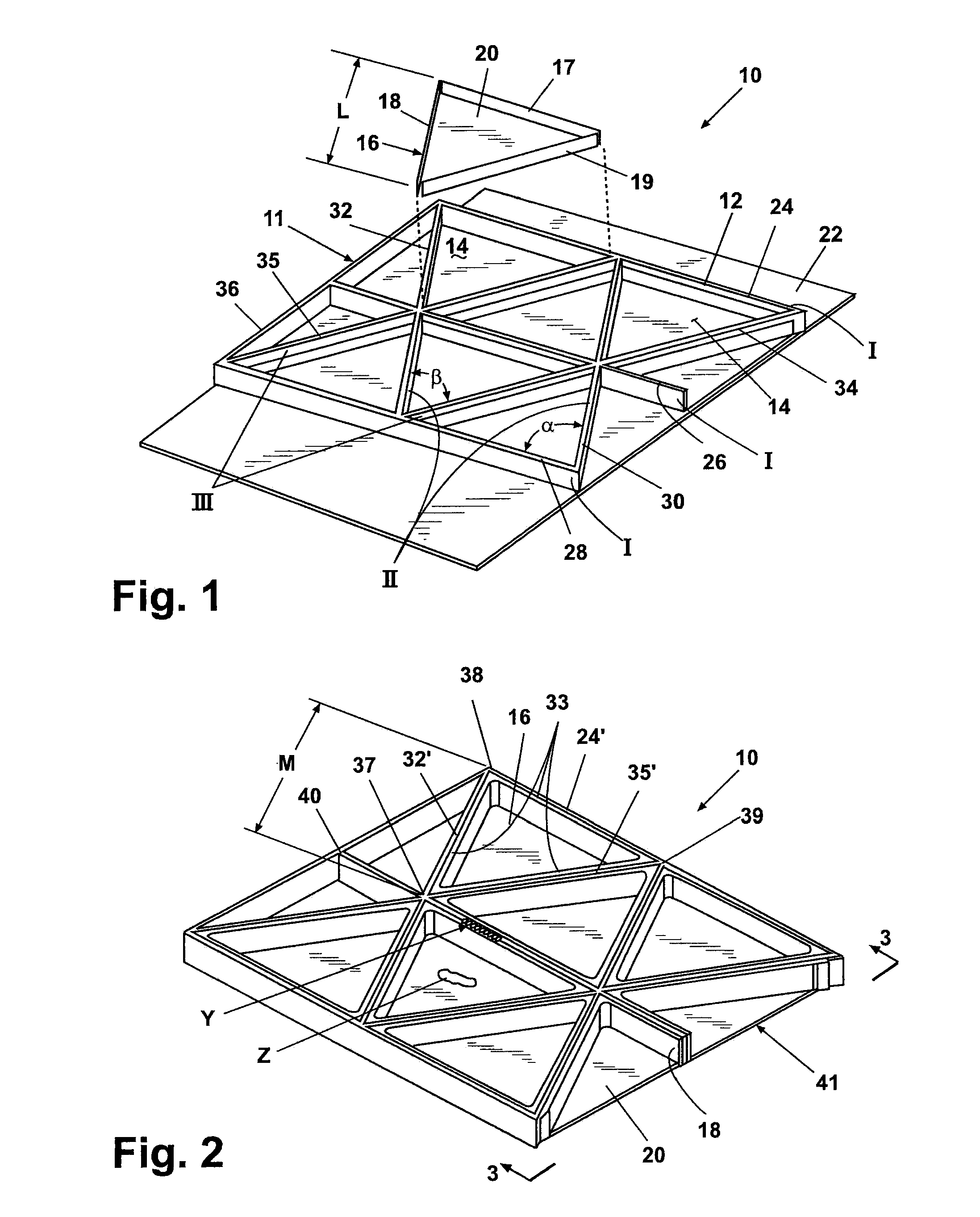
[0024]According to a preferred embodiment of the present invention and referring generally to FIG. 1, a cellular composite structure 10 of the present invention includes a grid 11 having a plurality of intersecting ribs 12. Between the intersecting ribs 12 a plurality of apertures or cavities 14 are created. The cavities 14 have a closed geometric shape shown as a regular triangular shape, however, the invention is not limited to triangular shaped cavities. Other shapes including but not limited to rectangles, squares diamonds, parallelograms, hexagons and the like can also be used. Similarly shaped aircraft structural members are disclosed in U.S. patent application Ser. No. 10 / 846,861, filed May 14, 2004, the disclosure of which is incorporated herein by reference. Generally, the cavities 14 are designed to have the s...


PUM

PropertyMeasurementUnit
thicknessaaaaaaaaaa
temperatureaaaaaaaaaa
temperaturesaaaaaaaaaa

Abstract

A cellular composite structure includes a grid having groups of angularly intersecting ribs. The ribs of each group are oriented substantially in the same direction to each other and angularly oriented from the other rib groups. An additional rib defines a composite structure outer perimeter wall and can be differently angularly oriented from the other ribs. A contiguous rib wall is created by segments of ribs defined by rib intersections. The contiguous rib wall bounds a cavity. A multilayer sheet cap member with extending walls to engage the contiguous rib wall is positioned within the cavity. The engagement walls extend from individual sheet perimeter portions angularly oriented to the sheet. The ribs and cap member have pre-impregnated resin. Heating the cap member and ribs activates the resin and co-cures the composite structure.

Description

CROSS-REFERENCE TO RELATED APPLICATIONS[0001]This application is a divisional of U.S. patent application Ser. No. 11 / 048,177 filed on Feb. 1, 2005. The entire disclosure of the above application is incorporated herein by reference.FIELD OF THE INVENTION[0002]The present invention relates in general to grid structures and more specifically to a composite material grid-stiffened structure and method of manufacture.BACKGROUND OF THE INVENTION[0003]Metallic grid-stiffened structures have been used in aerospace and other industry applications due to their structural efficiency as stiffened panels, shells and tanks. Composite grid-stiffened structures provide a better strength-to-weight ratio for these applications resulting in lower weight and increased payload capacity. Composite grid-stiffened structures also provide an alternative to honeycomb-core structures. Grid stiffened structures have no moisture entrapment problems and require no core forming, placement and / or potting.[0004]Cur...

Claims


Application Information

Patent Timeline
Patent Type & Authority Applications(United States)
IPC IPC(8): B29C65/00
CPCB29C70/342Y10T156/1051B32B5/12B32B5/26B32B2260/023B32B2260/046B32B2262/106B32B2307/5825B32B2605/18Y02T50/433Y10T428/24612Y10T428/24661Y10T428/24157Y10T428/2457B32B3/12B29C70/549Y02T50/40
Inventor LEE, SHIN S.VANWEST, BARRY P.
Owner THE BOEING CO
Why Eureka
Try Eureka