
Phosphor for Display and Field Emission Display

a field emission display and phosphor technology, applied in the direction of discharge tube luminescent screen, discharge tube/lamp details, luminescent composition, etc., can solve the problem of significantly long excitation time compared to crts, low current density per unit time obtainable by electron beam, shorten the lifetime of phosphor, etc. problem, to achieve the effect of excellent luminous efficiency, long lifetime and high luminan

Inactive Publication Date: 2009-02-12
CANON KK
View PDF17 Cites 6 Cited by
  • Summary
  • Abstract
  • Description
  • Claims
  • Application Information

AI Technical Summary

Benefits of technology

[0007]The present invention is made to overcome the above-described problems and aims to provide a phosphor for a displays having a high luminance. It is also an object of the present invention to provide a field emission display (FED) having a high luminance and excellent display characteristics such as color reproducibility by using such a phosphor.
[0010]Since the phosphor for the display of the present invention contains, as a matrix, strontium thiogallate (SrGa2S4), i.e., a ternary compound of strontium (Sr), gallium (Ga), and sulfur (S), and, as an activator, europium (Eu) whose electronic state makes transition from the ground level to an excited level at a high probability, excellent luminous efficiency is achieved by irradiation with a pulse electron beam having an accelerating voltage of 5 to 15 kV, and high luminance is obtained.
[0011]Compared to zinc sulfide phosphors and oxysulfide phosphors that have been used as the phosphors for CRTs in the related art, long lifetime is achieved. Thus, when the phosphor for the display is used, a thin, flat display, such as a FED, having a high luminance, excellent display characteristics, and a long lifetime can be realized.

Problems solved by technology

However, the accelerating voltage (excitation voltage) of the electron beam is lower than that of CRTs, and the current density per unit time obtainable by the electron beam is also low.
Thus, in order to achieve a sufficient luminance, a significantly long excitation time is required compared to CRTs.
This means that the quantity of charges injected per unit area needs to be increased to achieve a particular luminance, and this shortens the lifetime of the phosphor.
Consequently, sufficient luminance and lifetime have not been obtained with zinc sulfide-based phosphors that have been used in CRTs in the related art.
However, in FEDs having an excitation voltage of 5 to 15 kV, it is not likely that this phosphor can be directly used.

Method used


Image

  • Phosphor for Display and Field Emission Display
  • Phosphor for Display and Field Emission Display
  • Phosphor for Display and Field Emission Display

Examples


example 1

[0040]Starting materials containing elements constituting the matrix of the phosphor and the activator or compounds containing such elements were weighed so that the stoichiometric ratio of the composition shown in Table 1 (SrGa2S4:Eu, Eu content being 2 mol %) was achieved, and thoroughly mixed. The resulting phosphor material was filled in a quartz crucible with adequate amounts of sulfur and activated carbon, and fired in a hydrogen sulfide atmosphere. The firing condition was 800° C.×60 min.

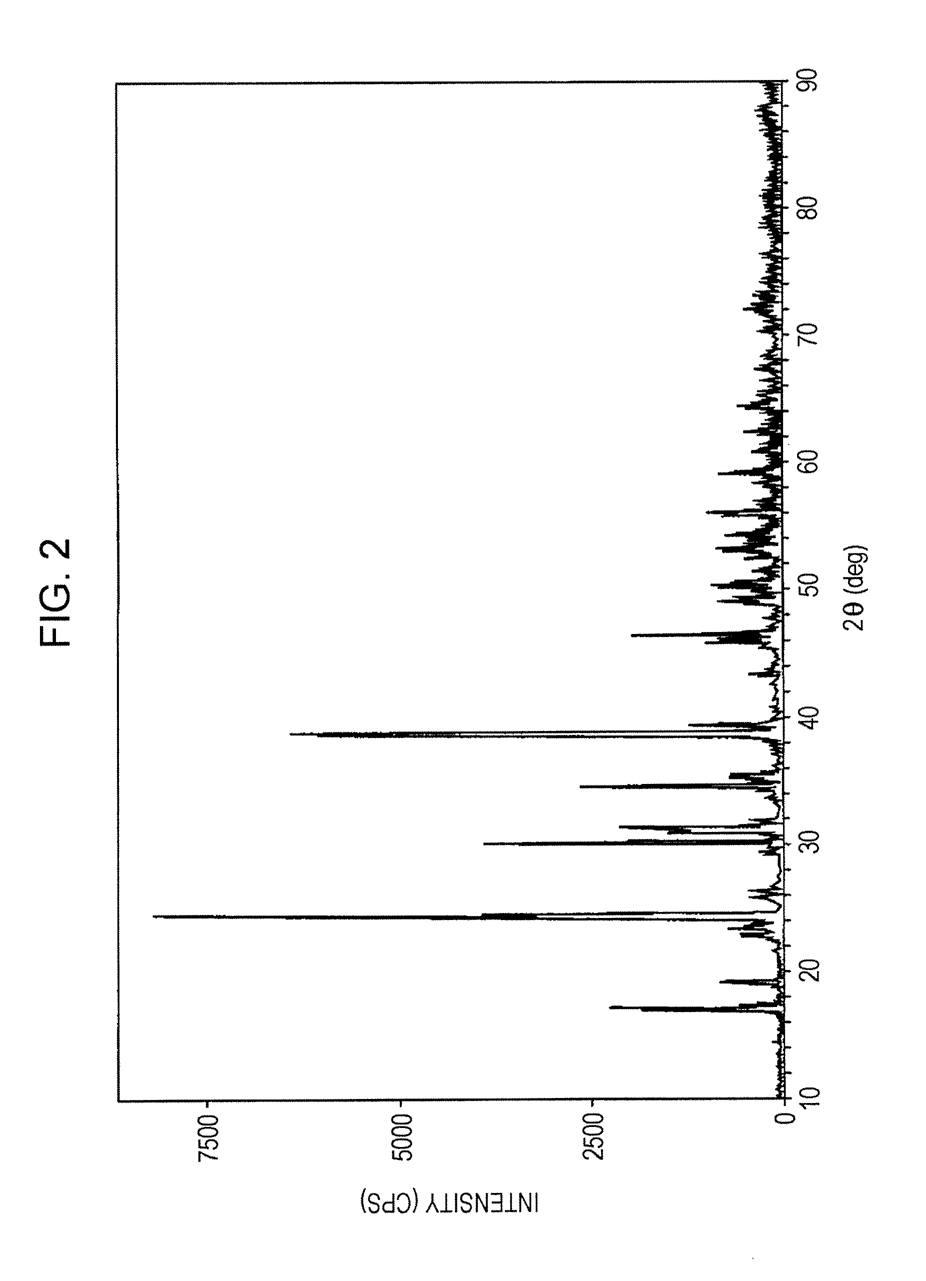
[0041]The resulting fired material was washed with water, dried, and sieved to obtain a europium (Eu)-activated strontium thiogallate phosphor (SrGa2S4:Eu) . An XRD (X-ray diffraction) spectrum of the obtained europium-activated strontium thiogallate was measured, and an XRD (X-ray diffraction) pattern shown in FIG. 2 was obtained. No peak was found in the diffraction angle (2θ) range of 27° to 29° in the XRD pattern, which confirmed that the europium-activated strontium thiogallate phosphor ...

example 2

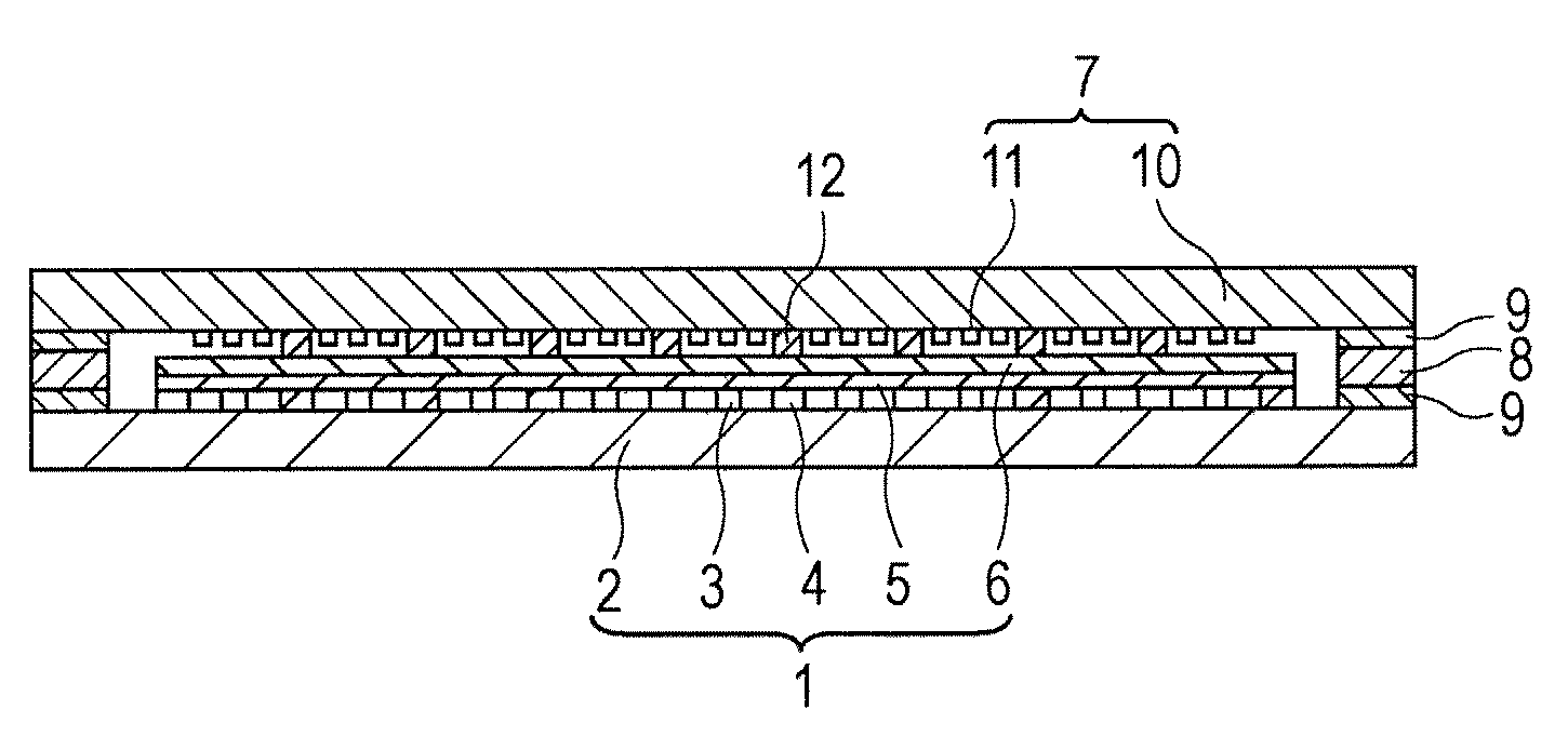
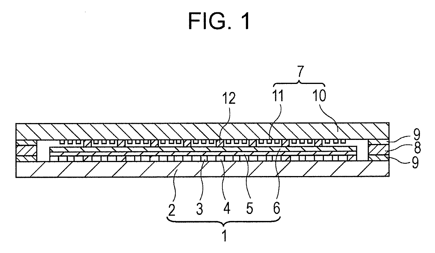
[0047]The europium (Eu)-activated strontium thiogallate phosphor (SrGa2S4:Eu) obtained in Example 1, a known blue light emitting phosphor (ZnS:Ag,Al), and a known red light emitting phosphor (Y2O2S:Eu) were used to form phosphor layers on a glass substrate to thereby form a face plate. The face plate was assembled with a rear plate having many electron emitting elements with a supporting frame, and the gap between the plates was hermetically sealed under vacuuming. It was confirmed that the FED thus produced exhibited excellent color reproducibility including luminance and that satisfactory luminance characteristic was exhibited after 1000 hours of driving under rated operation.


PUM

PropertyMeasurementUnit
accelerating voltageaaaaaaaaaa
aaaaaaaaaa
excitation voltageaaaaaaaaaa

Abstract

Disclosed is a phosphor for displays which is characterized by being composed of a europium-activated thiogallate phosphor represented by the following chemical formula: SrGa2S4:Eu. This phosphor is also characterized by containing no gallium sulfide (Ga2S3) and being a green phosphor which emits light when excited by an electron beam having an accelerating voltage of 5-15 kV. Consequently, this invention provides a phosphor for displays having high luminance, which emits light when excited by a pulse electron beam having an accelerating voltage of 5-15 kV.

Description

TECHNICAL FIELD[0001]The present invention relates to a phosphor for displays and a field emission display incorporating the phosphor.BACKGROUND ART[0002]With advent of the multimedia age, for displays which are core devices of digital networks, achievement of increased screen size, higher definition, and compatibility with various sources such as computers is required.[0003]Among displays, field emission displays (FEDs) that use field emission elements such as field emission cold cathodes are currently being increasingly and extensively studied and developed as large-screen thin digital devices that can display various types of information at high density and with high definition.[0004]The basic display principle of the FEDs is the same as that of cathode ray tubes (CRTs), i.e., a phosphor is excited by electron beams so that the phosphor emits light. However, the accelerating voltage (excitation voltage) of the electron beam is lower than that of CRTs, and the current density per ...

Claims


Application Information

Patent Timeline
Patent Type & Authority Applications(United States)
IPC IPC(8): H01J63/04C09K11/77
CPCC09K11/7731H01J31/123H01J29/20
Inventor YOKOSAWA, NOBUYUKIYAMAGUCHI, KENICHI
Owner CANON KK
Learn More