Electrostatic loudspeaker driver

Inactive Publication Date: 2009-02-12
RICHTEK TECH
View PDF4 Cites 23 Cited by
  • Summary
  • Abstract
  • Description
  • Claims
  • Application Information

AI Technical Summary

Benefits of technology

[0010]The transformer can be alternatively disposed before the filter and in this case, the transformer operates in a high frequency range because of the PWM carrier in the digital signal. Thereby it may shrink the coil inductor size of the transformer and the whole size o

Problems solved by technology

The circuits of class-A or class-AB amplifiers are for analog designs, and a poor efficiency is realized in practical use with music signals.
The power is lost in the output devices significan

Method used


Image

  • Electrostatic loudspeaker driver
  • Electrostatic loudspeaker driver
  • Electrostatic loudspeaker driver

Examples


first embodiment

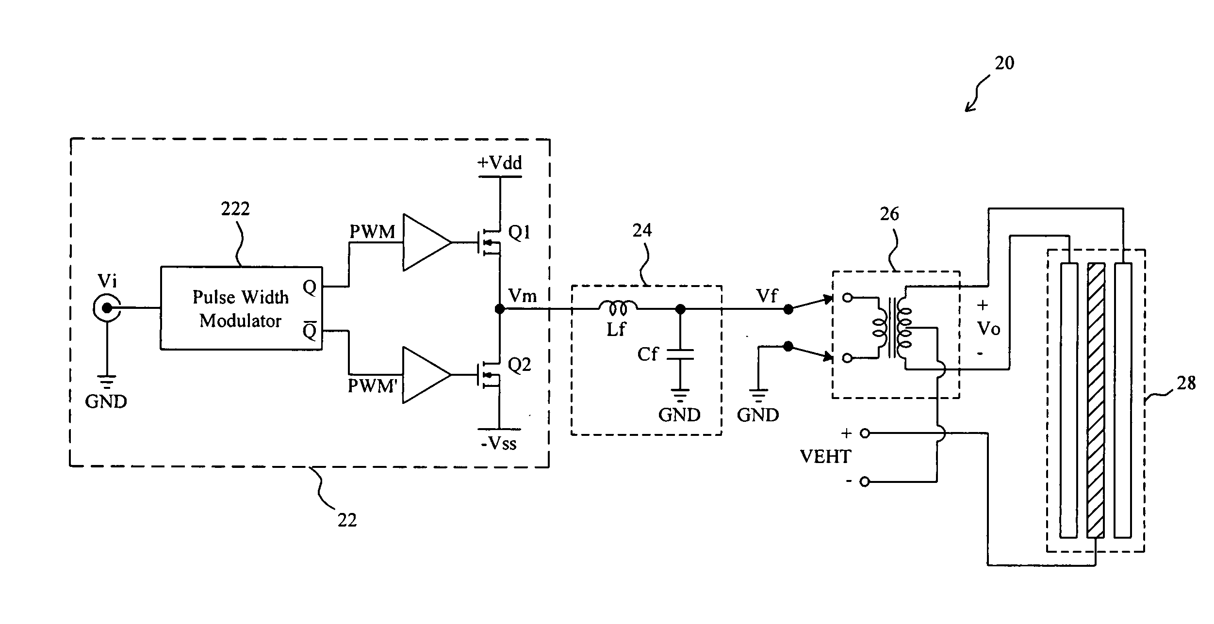
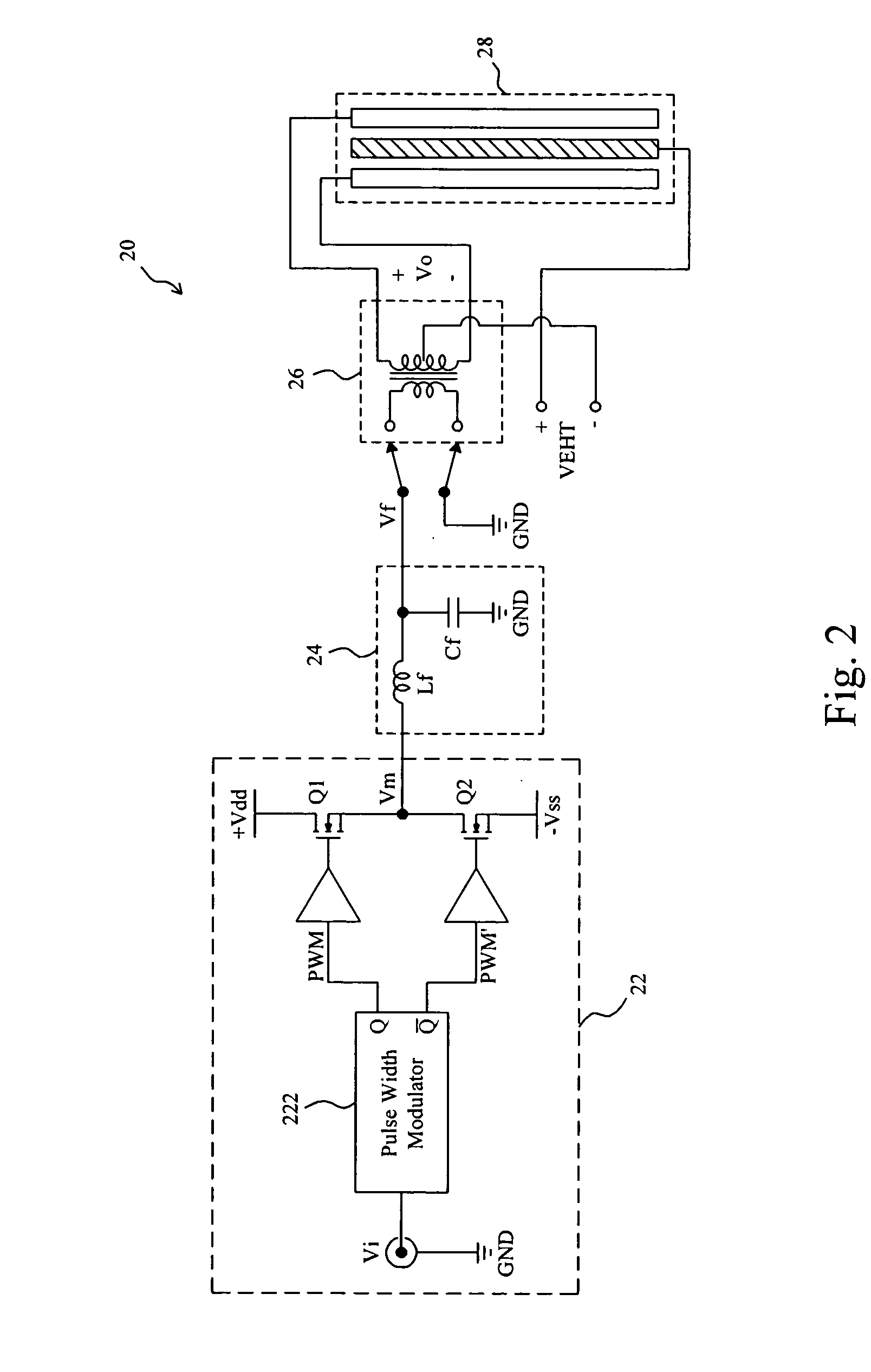
[0020]FIG. 2 shows a first embodiment according to the present invention. In an electrostatic loudspeaker driver 20, a half-bridge class-D amplifier 22 has an input to receive an input signal Vi and generates an amplified digital signal Vm accordingly, and a demodulator circuit which includes an L-C demodulator filter 24 and a step-up transformer 26 retrieves an audio signal from the digital signal Vm and produces an output signal Vo for driving an electrostatic loudspeaker 28. In the half-bridge class-D amplifier 22, two transistors Q1 and Q2 are serially connected between two power nodes +Vdd and −Vss, and a pulse width modulator 222 modulates the input signal Vi to generate pulse width modulation signals PWM and PWM′ to switch the transistors Q1 and Q2 respectively, so as to generate the digital signal Vm. A class-D amplifier is basically a switching amplifier. In this kind of amplifiers all power devices are operated in on / off state with a PWM signal, thereby reducing the power ...

second embodiment

[0021]FIG. 3 shows a second embodiment according to the present invention. In an electrostatic loudspeaker driver 30, a full-bridge class-D amplifier 32 has an input to receive an input signal Vi and generates two digital signals Vm and Vm′ accordingly, and a demodulator circuit which includes an L-C demodulator filter 34 and a step-up transformer 36 demodulates the digital signals Vm and Vm′ to generate an output signal Vo for driving an electrostatic loudspeaker 38. In the full-bridge class-D amplifier 32, four transistors Q1, Q2, Q3 and Q4 are configured with a full-bridge topology between two power nodes +Vdd and −Vss, and a pulse width modulator 322 modulates the input signal Vi to generate pulse width modulation signals PWM and PWM′ to switch the transistors Q1, Q2, Q3 and Q4 to generate the digital signals Vm and Vm′. In the demodulator circuit, the L-C demodulator filter 34 is a low-pass filter for filtering out the PWM carrier frequency in the digital signals Vm and Vm′ to ...

third embodiment

[0022]FIG. 4 shows a third embodiment according to the present invention. In an electrostatic loudspeaker driver 40, a half-bridge class-D amplifier 42 has an input to receive an input signal Vi and generates a digital signal Vm accordingly, and a demodulator circuit which includes a step-up transformer 44 and an L-C demodulator filter 46 demodulates the digital signal Vm to generate an output signal Vo for driving an electrostatic loudspeaker 48. In the half-bridge class-D amplifier 42, two transistors Q1 and Q2 are serially connected between two power nodes +Vdd and −Vss, and a pulse width modulator 422 modulates the input signal Vi to generate pulse width modulation signals PWM and PWM′ to switch the transistors Q1 and Q2 respectively, so as to generate the digital signal Vm. In the demodulator circuit, the transformer 44 transforms the digital signal Vm into a higher voltage signal Vt, and the L-C demodulator filter 46 filters out the PWM carrier frequency in the signal Vt to re...


PUM


Abstract

An electrostatic loudspeaker driver includes a class-D amplifier and a demodulator circuit. The class-D amplifier is operated with a PWM signal, creating an amplified digital signal according to an input signal. A low-pass filter in the demodulator circuit filters out the PWM carrier frequency in the digital signal and retrieves an audio signal therefrom. The efficiency is improved significantly and heat sink is no longer needed.

Description

FIELD OF THE INVENTION[0001]The present invention is related generally to an electrostatic loudspeaker (ESL) driver and, more particularly, to an electrostatic loudspeaker driver constructed with a class-D topology.BACKGROUND OF THE INVENTION[0002]Electrostatic loudspeakers have the advantages of extremely light weight and excellent frequency response. As shown in FIG. 1, an electrostatic loudspeaker 10 includes a very thin flat plastic membrane 16 suspended between two electrodes 12 and 14. Each of the electrodes 12 and 14 is a grid or a stator, and when a pair of positive and negative voltages V+, V− with a same magnitude are applied on the electrodes 12 and 14, the membrane 16 is attracted or repelled by the electrodes 12 and 14 and thus vibrates to produce a sound wave. To generate sufficient field strength between the electrodes 12 and 14, the audio signal applied on the electrodes 12 and 14 must be of high voltage. Typical audio amplifiers can't drive two electrodes in the ord...

Claims


Application Information

Patent Timeline
IPC IPC(8): H03G5/16
CPCH03F3/217
Inventor GUO, JWIN-YENTAI, LIANG-PINCHANG, SHAO-MING
Owner RICHTEK TECH
Why Eureka
Try Eureka