Magnetic bearing device

Inactive Publication Date: 2009-02-19
NTN CORP
View PDF4 Cites 12 Cited by
  • Summary
  • Abstract
  • Description
  • Claims
  • Application Information

AI Technical Summary

Benefits of technology

[0030]Where the compressive expansion turbine system, to which the magnetic bearing device is applied, is applied to the air cycle refrigerating system of the kind referred to the seventh construction, in the compressive expansion turbine system, the stabilized high speed revolution of the main shaft can be obtained with the proper rotor tip clearance maintained and, also, the long term durability of the bearing can be increased. Accordingly, the reliability of the

Problems solved by technology

Change in clearance constitutes a cause of an unstable operation during high speed rotation and, therefore, the efficiency tends to be lowered.
For this reason, the thrust load such as described above tends to bring about a reduction in long-term durability and lifetime of the bearing unit used to support the main shaft and, in turn, a reduction in reliability of the air cycle refrigerating turbine unit.
Unless the problem associated with the long-term durability of the bearing unit is resolved, the air cycle refrigerating turbine unit can be hardly placed in practical use.
However, the technology disclosed in the Japanese Patent No. 2623202 has not yet resolved the problem associated with the reduction in long-term durability of the bearing unit relative to the loading of the thrust load under such a high speed revolution.
For this reason, the presence of a factor or the like that render the control of the thrust bearing unit to be unstable makes it difficult to achieve a stabilized high speed revolution while the minute clearance is maintained between the rotor and the diffuser.
The magnetic bearing unit involves a problem associated with a contact between the rotor and the diffuser at the time of failure of t

Method used


Image

  • Magnetic bearing device
  • Magnetic bearing device
  • Magnetic bearing device

Examples


first embodiment

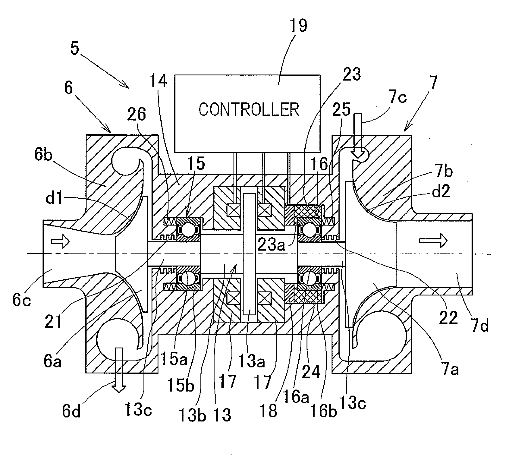
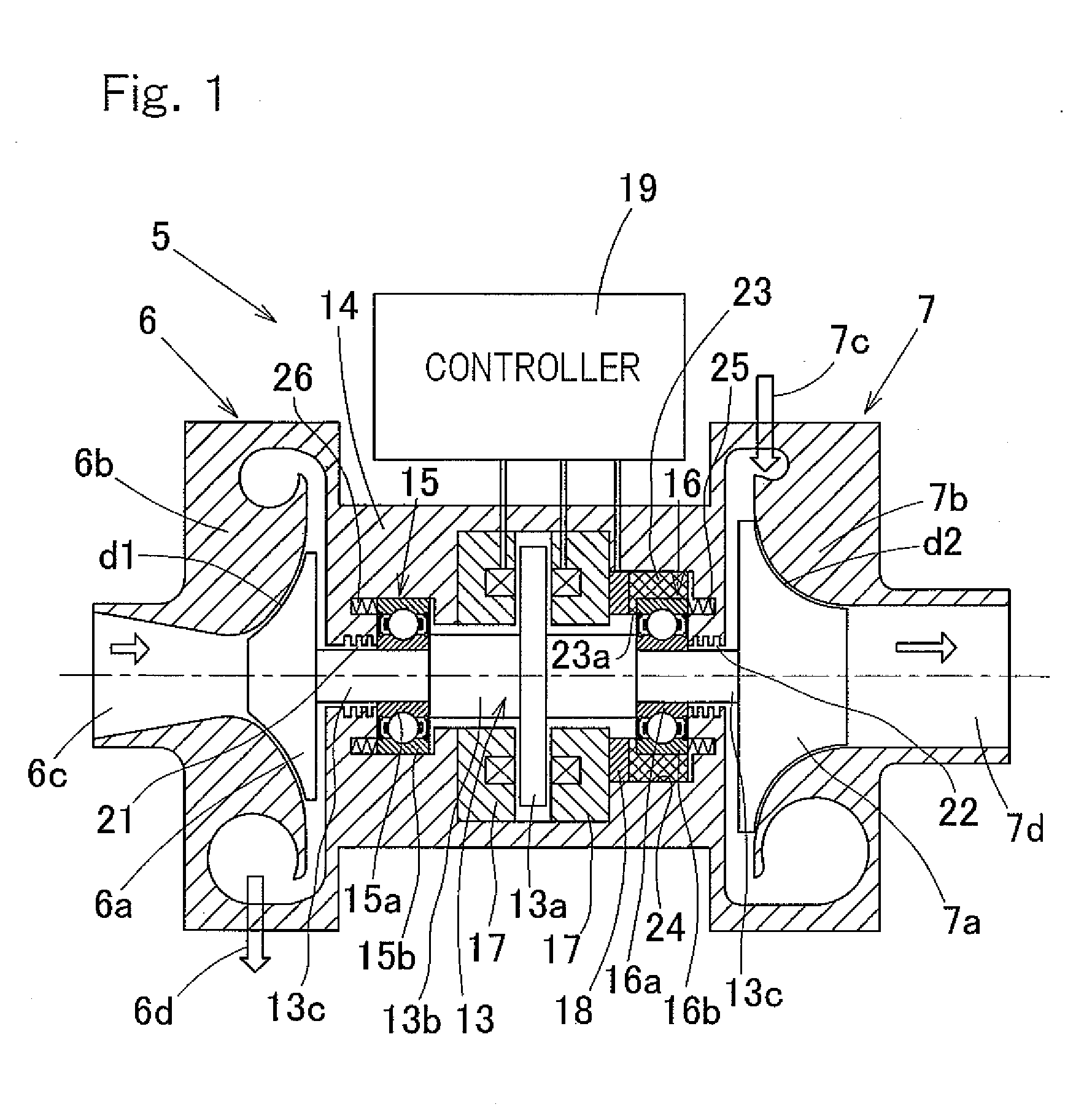
[0046]The first preferred embodiment of the present invention will be described with particular reference to FIGS. 1 and 2. FIG. 1 illustrates a sectional view showing a turbine unit 5, which incorporates therein a magnetic bearing device according to the present invention. This turbine unit 5 forms a part of a compressive expansion turbine system and includes a compressor 6 and an expansion turbine 7, and a compressor rotor 6a of the compressor 6 and an turbine rotor 7a of the expansion turbine 7 are mounted on opposite ends of a main shaft 13, respectively. Also, the compressor rotor 6a referred to above is driven by a power induced by the turbine rotor 7a and, accordingly, no extra drive source is employed.

[0047]The compressor 6 includes a housing 6b opposed to the compressor rotor 6a with a minute clearance d1 intervening therebetween and is operable to compress an air, sucked axially from a suction port 6c at a center portion thereof by means of the compressor rotor 6a and then...

second embodiment

[0068]In view of the above, in the magnetic bearing device in order to maintain the relation in magnitude as expressed by the formula (2) above, it is clear from the relationship between the formulas (3) and (4) that the electromagnet gaps d have to be so chosen as to satisfy the following formula (5):

d>k×Fmax / Kbrg  (5)

[0069]As discussed above, when the electromagnet gaps d are so chosen as to satisfy the condition expressed by the formula (5) above, it is possible to satisfy the relation in magnitude expressed by the formula (2) above as even under the condition, in which the bearing preload is so low as to suit in the region of high speed revolutions. As a result thereof, in the control region, it is possible to avoid the phase of the mechanical system from being retarded 180° and, accordingly, even when the maximum load acts, the target to be controlled by the controller 19 can be stabilized and controller 19 can have a circuit configured simply by utilizing proportional cont...

third embodiment

[0083]It is, however, to be noted that this construction makes it difficult to achieve the efficient utilization of a space in arranging the permanent magnet 20 and the coils 17b therein. By way of example, in such case, if an attempt is made to allow the electromagnet 17 to generate the same magnetic force of attraction as that exerted by the electromagnet 17 of the structure, in which the integral ring-shaped permanent magnet 20 is accommodated within the yoke 17a such as in the third embodiment shown in and described with reference to FIG. 4, the permanent magnet 20 will be required to have an increased thickness and, for this reason, the leakage of the magnetic fluxes will increase, resulting in an increase of the electric power consumed by the coils 17b for attenuating the magnetic force of attraction of the permanent magnet 20.

[0084]A fifth preferred embodiment of the present invention will now be described with particular reference to FIGS. 9 to 12 together with FIG. 2 employ...


PUM


Abstract

A magnetic bearing device includes a main shaft (13), a flange shaped thrust plate (13a) coaxially mounted on the main shaft so as to extend perpendicular to the main shaft and made of a ferromagnetic material, a rolling bearing unit for supporting a radial load and a magnetic bearing unit for supporting one or both of an axial load and a bearing preload, an electromagnet (17) fitted to a spindle housing (14) so as to confront the thrust plate, without contact, a sensor (18) for detecting an axial force acting on the main shaft, and a controller (19) for controlling the electromagnet in response to an output from the sensor. In this magnetic bearing device, the stiffness of a composite spring formed by the rolling bearing unit and a support system for the rolling bearing unit is so chosen as to be higher than the negative stiffness of the electromagnet.

Description

BACKGROUND OF TEE INVENTION[0001]The present invention relates to a magnetic bearing device concurrently utilizing a rolling bearing unit and a magnetic bearing unit and utilizable in, for example, a turbine unit in an air cycle refrigerating system, in which the magnetic bearing device is operable to support one or both of an axial load and a bearing preload.[0002]The air cycle refrigerating system makes use of an air as a refrigerating medium and does therefore fail to exhibit a sufficient energy efficiency as compared with the refrigerating system using chlorofluorocarbon or ammonium, but is considered agreeable in terms of environmental protection. Also, in a facility such as, for example, a cold storage warehouse into which a refrigerating air can be directly blown, the total cost can be lowered if a cooling fan device and / or defroster are dispensed with, and, accordingly, the use of the air cycle refrigerating system in such application has been suggested. (See, for example, t...

Claims


Application Information

Patent Timeline
IPC IPC(8): F16C33/00F25D9/00
CPCF01D15/005F04D29/051F04D29/058F04D29/059F16C2362/52F16C25/08F16C39/06F05D2240/51F05D2240/515F16C19/54
Inventor OZAKI, TAKAYOSHIYAMADA, HIROYUKISUZUKI, KENICHI
Owner NTN CORP
Why Eureka
Try Eureka