Fiducial Marker for Correlating Images

a technology of image correlation and fiducial markers, applied in the field of fiducial markers, can solve the problems of inability to detect the lack of alignment in the image, the inability of the light microscope objective to visualize the actual location of the x-ray beam, and the inability to provide fiducials, etc., to achieve the effect of enhancing the ability to analyze a thin sampl

Inactive Publication Date: 2009-02-19
BROOKHAVEN SCI ASSOCS
View PDF3 Cites 18 Cited by
  • Summary
  • Abstract
  • Description
  • Claims
  • Application Information

AI Technical Summary

Benefits of technology

[0011]The invention relates to a fiducial marker for correlating a first analytical image produced by a first imaging modality with at least one second image produced by at least one second modality. The ability to make the correlation between the two images enhances the ability to analyze a thin sample. The fiducial marker of the present invention comprises a sample substrate having a surface, and a marking grid composed of a metallic material that is substantially free of contaminants that would interfere with the desired measurement of ppm (parts per million) concentrations of for example trace metal ions in the thin sample. The marking grid has a grid pattern that is coated on the surface of the substrate. The grid pattern is imageable by the first imaging modality and at least one second modality. The second modality can be either a viewing modality or an analytical modality. The first analytical image overlaps the at least one second image to achieve the correlation. Thus, the fiducial marker can be used to correlate the first analytical image produced by an x-ray beam of an x-ray fluorescence microprobe with the second modality that is a light microscope objective for producing a viewing image of the thin sample. The grid pattern is imageable by x-ray fluorescence microprobe and the light microscope objective where the x-ray beam cannot be visualized by the light microscope objective.

Problems solved by technology

Yet most of the abovementioned studies utilize only a fraction of the available tools, and therefore, do not examine every aspect of the disease.
One problem recognized as extant is the provision of fiducials capable of use with more than one imaging modality.
However, the light microscope objective is unable to visualize the actual location of the x-ray beam.
This can be a challenge as any motion in the x-ray beam or the visible light optics can prevent precise overlapping.
Further, the lack of alignment in the images is not detected during data analysis and collection because the x-ray beam is not visible.

Method used


Image

  • Fiducial Marker for Correlating Images
  • Fiducial Marker for Correlating Images
  • Fiducial Marker for Correlating Images

Examples


examples

1. Single Deposition Process of the Present Invention (5 μm)

[0061]A. Chromium Deposition Sequence

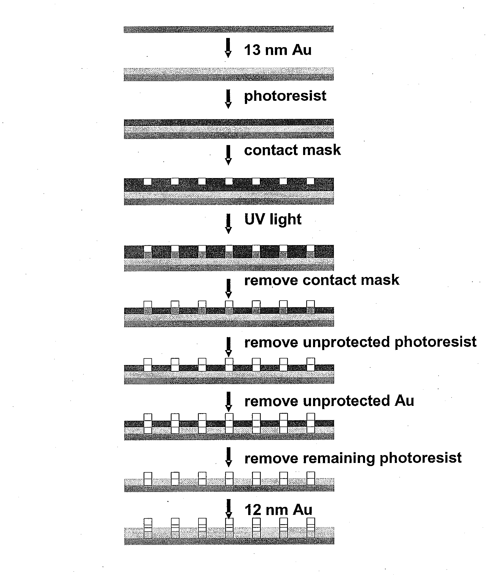
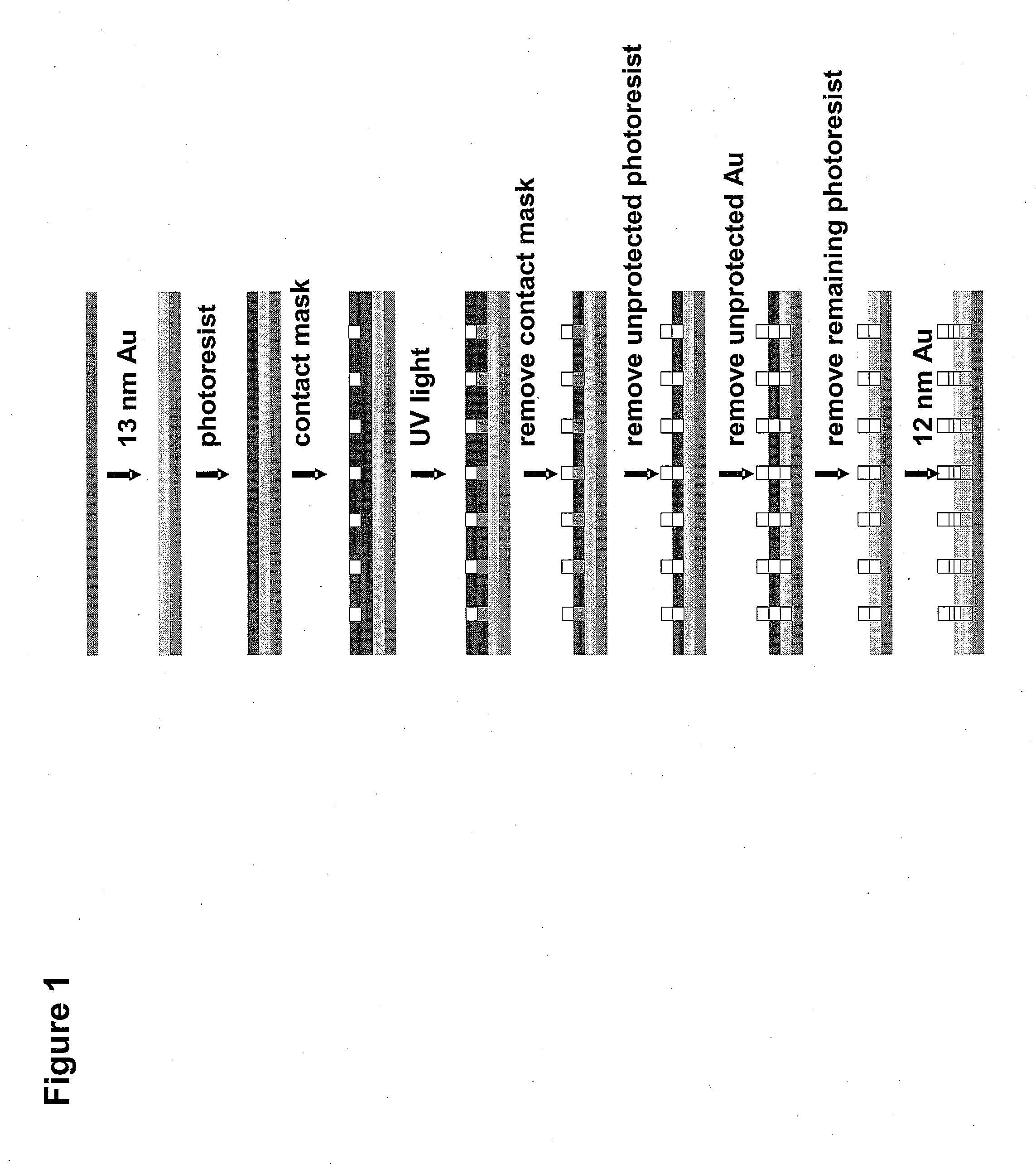
[0062]To produce the grid pattern on the substrate with chromium as the metal of the marking grid, a single deposition process is used. A 2 inch diameter high-purity quartz disc (quartz wafer), the substrate, is washed in an aqueous solution containing “Micro” laboratory cleaner (International Products Corp., Burlington, N.J., 08016) in an ultrasonic cleaner to remove organic films from the substrate. The substrate is rinsed with deionized water and then placed in boiling isopropanol to ensure that any residual water goes into solution and is removed from the substrate. To remove any adsorbed water monolayers, the substrate is baked for 30 min. at 120° C. Immediately after baking, the substrate is placed in a vacuum evaporator very close to a crystal thickness monitor and the system is pumped to achieve a vacuum better than 10−6 torr.

[0063]A small tungsten wire basket is filled with chro...


PUM


Abstract

The invention relates to a fiducial marker having a marking grid that is used to correlate and view images produced by different imaging modalities or different imaging and viewing modalities. More specifically, the invention relates to the fiducial marking grid that has a grid pattern for producing either a viewing image and/or a first analytical image that can be overlaid with at least one other second analytical image in order to view a light path or to image different imaging modalities. Depending on the analysis, the grid pattern has a single layer of a certain thickness or at least two layers of certain thicknesses. In either case, the grid pattern is imageable by each imaging or viewing modality used in the analysis. Further, when viewing a light path, the light path of the analytical modality cannot be visualized by viewing modality (e.g., a light microscope objective). By correlating these images, the ability to analyze a thin sample that is, for example, biological in nature but yet contains trace metal ions is enhanced. Specifically, it is desired to analyze both the organic matter of the biological sample and the trace metal ions contained within the biological sample without adding or using extrinsic labels or stains.

Description

[0001]The present invention was made with government support under Contract No. DE-AC02-98CH10886 awarded by the U.S. Department of Energy. The United States government has certain rights in the invention.FIELD OF THE INVENTION[0002]The invention relates to a fiducial marker having a grid that is used to correlate and view images produced by different imaging modalities. More specifically, the invention relates to the fiducial marking grid having a grid pattern used to produce viewing and analytical images that are overlaid and correlated to view a light path or to image different imaging modalities.BACKGROUND OF THE INVENTION[0003]Many disease processes involve alterations in the chemical makeup of tissue. Synchrotron-based infrared (IR) and x-ray fluorescence microscopes (XRFM) are becoming increasingly popular for imaging both organic and trace metal compositions of biological cells and tissues, respectively, without the need for extrinsic labels or stains. Coupled with visible l...

Claims


Application Information

Patent Timeline
Patent Type & Authority Applications(United States)
IPC IPC(8): A61B5/05
CPCG01N23/223G01N2223/076G02B21/367
Inventor MILLER, LISA MARIESMITH, RANDY J.WARREN, JOHN B.ELLIOTT, DONALD
Owner BROOKHAVEN SCI ASSOCS
Why Eureka
Try Eureka