
Permselective Membrane Module And Method For Manufacturing The Same

Active Publication Date: 2009-02-26
TOYO TOYOBO CO LTD
View PDF8 Cites 16 Cited by
  • Summary
  • Abstract
  • Description
  • Claims
  • Application Information

AI Technical Summary

Benefits of technology

[0064]In the method for manufacturing a permselective membrane module according to the invention, the use of premolded holders can remarkably improve the production yield, durability, and quality of the module. Moreover, the permselective membrane module produced by the method of the invention allows suspended solids to effectively float over the membrane surface, while being excellent at discharging the suspended solids from the system, thus resulting in a reduction in cleaning costs. In addition, excellent performance recovery of the permselective membrane module can lengthen the element life. Furthermore, the replacement of membranes involves only the replacement of an element, thereby reducing the water filtration cost.

Problems solved by technology

Thus, although suspended solids on the surface of the membranes near the center of the membrane bundles can be removed by cleaning, it is difficult to efficiently discharge the solids to the outside of the bundles, causing the possibility of re-deposition on the membrane surface.
In a large module, however, even if air is introduced from the outer periphery of the bundles, the air does not reach the hollow fiber membranes near the center of the membrane bundles.
This results in problems such as the inability to clean suspended solids on the surface of hollow fiber membranes near the center of the membrane bundles.
However, because the hollow fiber membranes in the U-shaped region are not fixed, the membranes are strongly shaken during air scrubbing, resulting in possible membrane breakage.
Moreover, during this shaking, friction is produced between the membranes and the binding member that is used to form the U-shape, resulting in possible membrane breakage.
This requires the additional task of pulling off the tubular material, and may also cause poor sealing if the resin for sealing the membranes in contact with the tubular material is removed together when pulling off the tubular material.
Moreover, if a resin with high rigidity, such as epoxy resin, is used, the resin may crack while removing the tubular material.
In addition, it is very difficult to locate the tubular material in a predetermined position by binding it with hollow fiber membranes.
When inserting hollow fiber membranes with the tubular material being fixed at a predetermined position, the tubular material must be avoided while inserting the membranes, resulting in possible breakage of the membranes in contact with the tubular material.
This configuration requires opening and closing the valves, as well as switching flow paths for each filtration and cleaning cycle, thus complicating the operation of a filtration apparatus composed of this hollow fiber membrane module.
Moreover, the location of the air release valve on the side surface of the vessel results in incomplete discharge of air from the module.
This incomplete discharge of air further increases the possibility of suspended solids adsorbing onto the hollow fiber membranes.
Whereas this kind of configuration is applicable to relatively small modules or modules with sections of specific shapes, it is difficult to apply to large modules or modules with sections of complicated shapes (shapes with relatively many acute angles).
Providing slits by these methods poses problems such as the resin cracking during processing, damage to the hollow fiber membranes, and unstable product quality.

Method used


Image

  • Permselective Membrane Module And Method For Manufacturing The Same
  • Permselective Membrane Module And Method For Manufacturing The Same
  • Permselective Membrane Module And Method For Manufacturing The Same

Examples


example 1

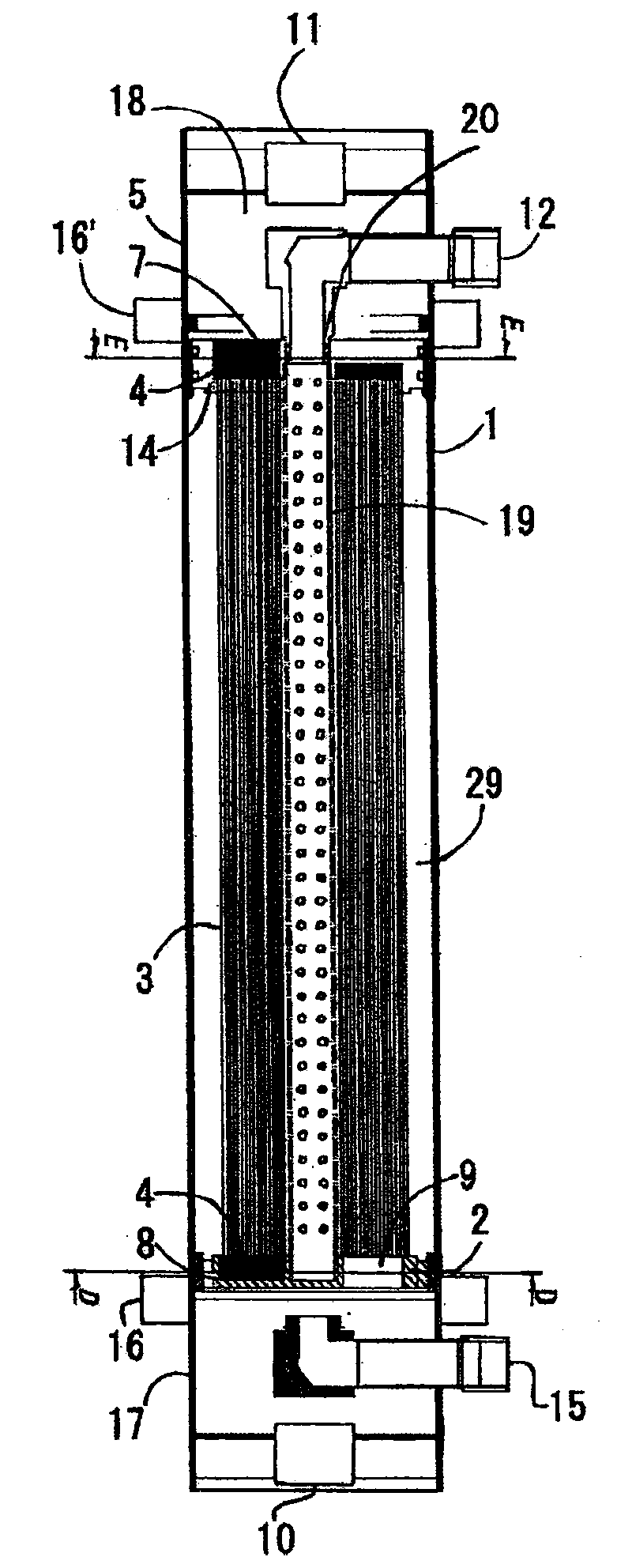
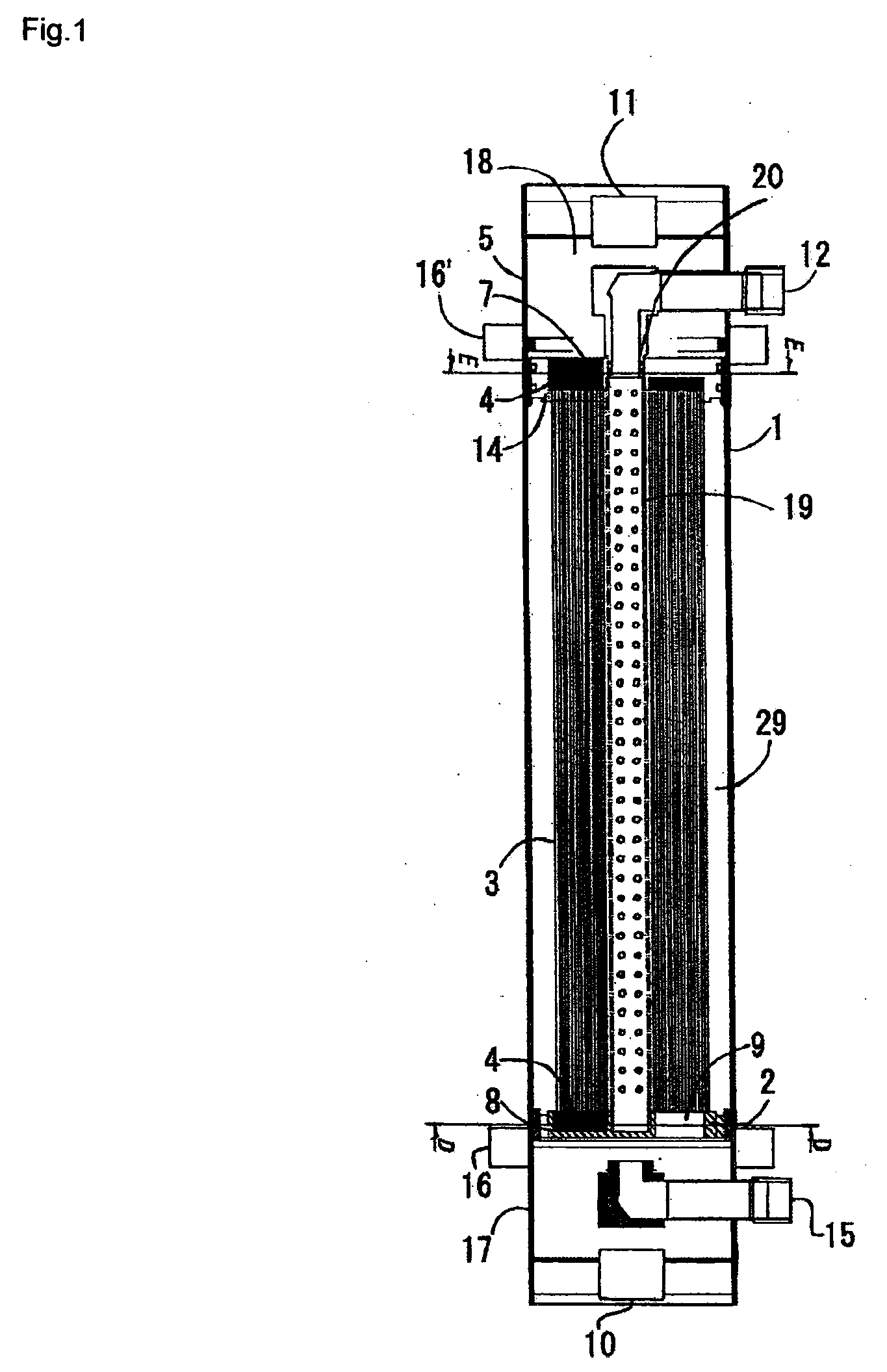
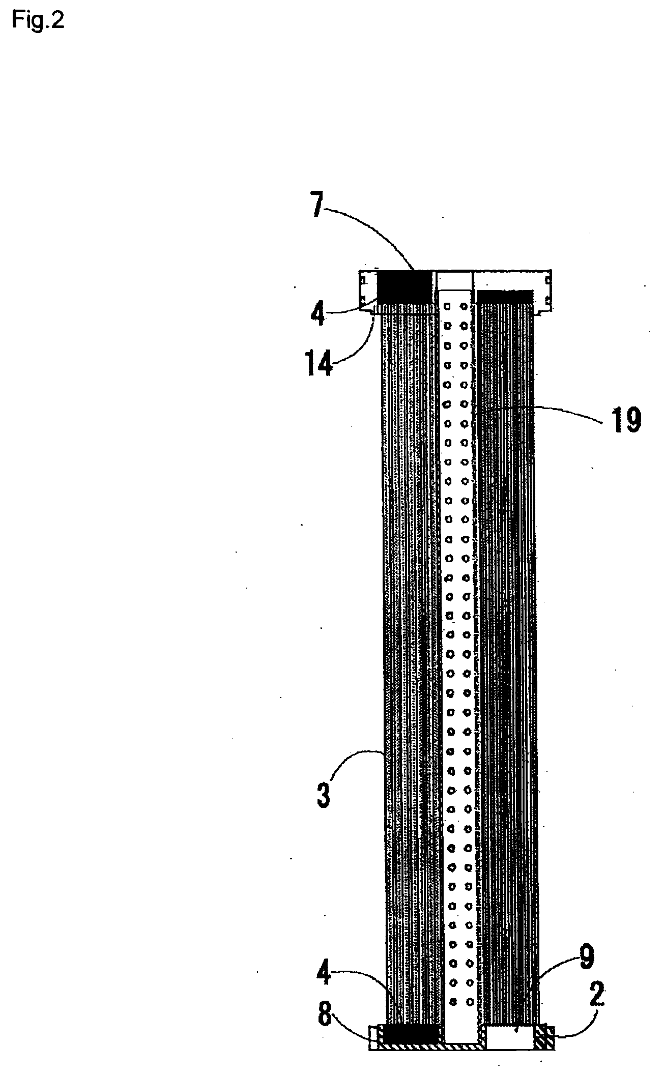
[0125]Each end of a cleaning pipe was connected with a polyvinyl-chloride lower holder or upper holder having six sections and six premolded slits. In each section was inserted three bundles of polyethersulfone hollow fiber membranes, each bundle having an outer diameter of 1200 μm, an inner diameter of 700 μm, and a molecular weight cut-off of 300,000 daltons, and consisting of 960 membranes wound with a protective net. The bundles were then fixed by injecting polyurethane resin. After curing the polyurethane resin, a portion of the resin in the upper holder was cut off, together with the hollow fiber membranes, to provide open-ended membranes, thereby yielding a permselective membrane element. The upper holder had the configuration shown in FIG. 2. The lower holder, as shown in FIG. 3, had six projections, and slits with a width of 4 mm and a length of 74 mm which were positioned between sections and arranged radially from around the center of the holder. The cleaning pipe was mad...

example 2

[0130]To a polyvinyl-chloride cylindrical vessel with an outer diameter of 145 mm and a length of 1075 mm was attached polyvinyl-chloride holders with an outer diameter of 110 mm and a thickness of 40 mm. The holders had four sections for dividing hollow fiber membranes, and had slits with a width of 4 mm and a length of 20 mm between sections. A module vessel was then assembled, using a cleaning pipe which was made of polyvinyl chloride and had an inner diameter of 25 mm, a length of 1075 mm, and four perforations 5 mm in diameter positioned circumferentially around the side surface with a pitch of 45 mm, making a total of 88 perforations. Using polyethersulfone hollow fiber ultrafiltration membranes with an outer diameter of 1200 μm, an inner diameter of 700 μm, and a molecular weight cut-off of 300,000 daltons, eight bundles each of 420 membranes were prepared and put in a polyethylene protective net. Two bundles were inserted into each of the four sections of the filtration modu...

example 3

[0133]To a polyvinyl-chloride cylindrical vessel with an outer diameter of 216 mm and a length of 1000 mm were attached polyvinyl-chloride holders with an outer diameter of 192 mm and a thickness of 40 mm. The holders had six sections for dividing hollow fiber membranes, and had slits with a width of 4 mm and a length of 50 mm between sections. A module vessel was then assembled, using a cleaning pipe which was made of polyvinyl chloride and had an inner diameter of 25 mm, a length of 1075 mm, and four perforations 5 mm in diameter positioned circumferentially around the side surface with a pitch of 30 mm, making a total of 132 perforations. Using polyethersulfone hollow fiber ultrafiltration membranes with an outer diameter of 1200 μm, an inner diameter of 700 μm, and a molecular weight cut-off of 300,000 daltons, eight bundles each having 1200 membranes were prepared and put in a polyethylene protective net. Two bundles were inserted into each of the four sections of the filtratio...


PUM

PropertyMeasurementUnit
Permeabilityaaaaaaaaaa
Permselectivityaaaaaaaaaa

Abstract

To provide a method for manufacturing a module having a selectively permeable membrane wherein the surface of the selectively permeable membrane thereof can be washed with good efficiency and further contaminants having been exfoliated from the surface of the membrane by a washing operation can be discharged from the inside of a housing with good efficiency; and the above module having a selectively permeable membrane.A method for manufacturing a module having a selectively permeable membrane, characterized in that in the manufacture of a module wherein a selectively permeable membrane is held in a housing and both ends of the above selectively permeable membrane are fixed, the both ends of the above selectively permeable membrane are fixed to an upper holder and an under holder connected by at least one washing tube, and then, the membrane is held in the housing; and a module having a selectively permeable membrane manufactured by the above manufacturing method.

Description

TECHNICAL FIELD[0001]The present invention relates to a method for manufacturing permselective membrane modules which treat water containing suspended matter (hereinafter referred to as “raw water”), such as river water, lake water, ground water, brackish water, seawater or sewage, in order to remove particles, bacteria and the like from the water. More specifically, the invention relates to a permselective membrane module that can feed raw water uniformly to each permselective membrane, uniformly and efficiently clean solids such as suspended matter deposited on the membrane surface, and efficiently discharge the suspended solids that are peeled from the permselective membrane surface.BACKGROUND ART[0002]When raw water is filtered using a permselective membrane module directly or after pretreatment, a pressurized or submerged type module is generally employed. With the pressurized type, permselective membranes are housed in a vessel, and raw water is fed to the membranes by means o...

Claims


Application Information

Patent Timeline
IPC IPC(8): B01D69/10B29C65/00
CPCB01D63/02B01D65/02B01D2313/20B01D2313/46B01D2321/2058B01D2321/12B01D2321/168B01D2321/185B01D2313/48B01D2313/201
Inventor BABA, KOICHIYAGI, TOSHIYUKI
Owner TOYO TOYOBO CO LTD
Learn More