
Method and device for chromatographic purification

Active Publication Date: 2009-02-26
ETH ZZURICH
View PDF8 Cites 15 Cited by
  • Summary
  • Abstract
  • Description
  • Claims
  • Application Information

AI Technical Summary

Benefits of technology

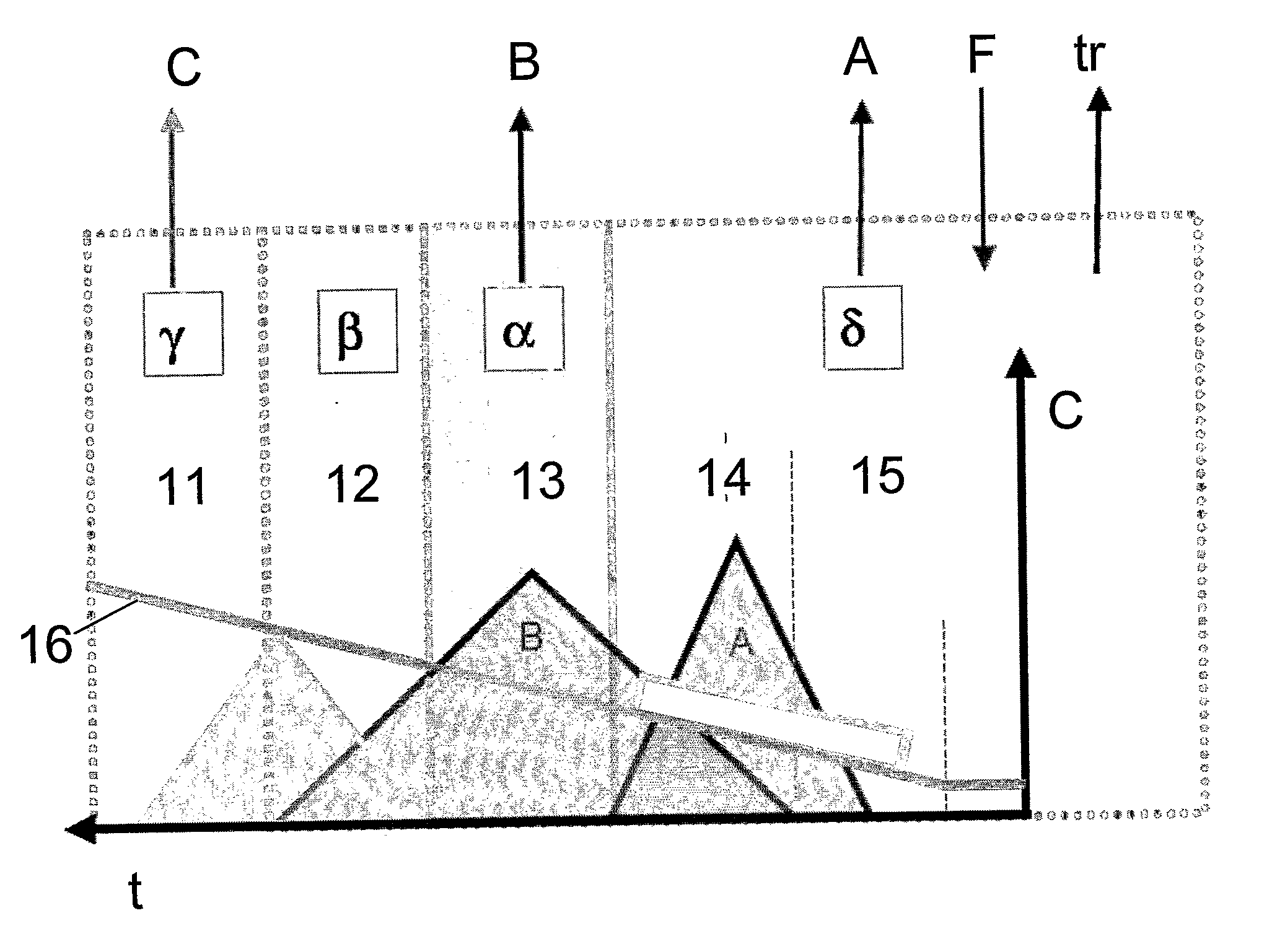
[0010]The objective of the present invention is therefore to provide an improved purification process, which allows to separate three fractions. The process shall be simple to set up in particular in view of large scale applications, and it shall allow a high purity and high yield. A process for continuous or quasi-continuous purification of a multi-component mixture is proposed by means of individual chromatographic columns through which the mixture is fed by means of at least one solvent. The aim of the process is not just separation of two fractions but the principal advantage is that a true multi-component mixture which at least comprises light impurities, an intermediate product to be purified and heavy impurities can be purified, i.e. an intermediate product can be isolated, and this even if this intermediate or desired product is only present in small amounts compared to the heavy and light impurities.
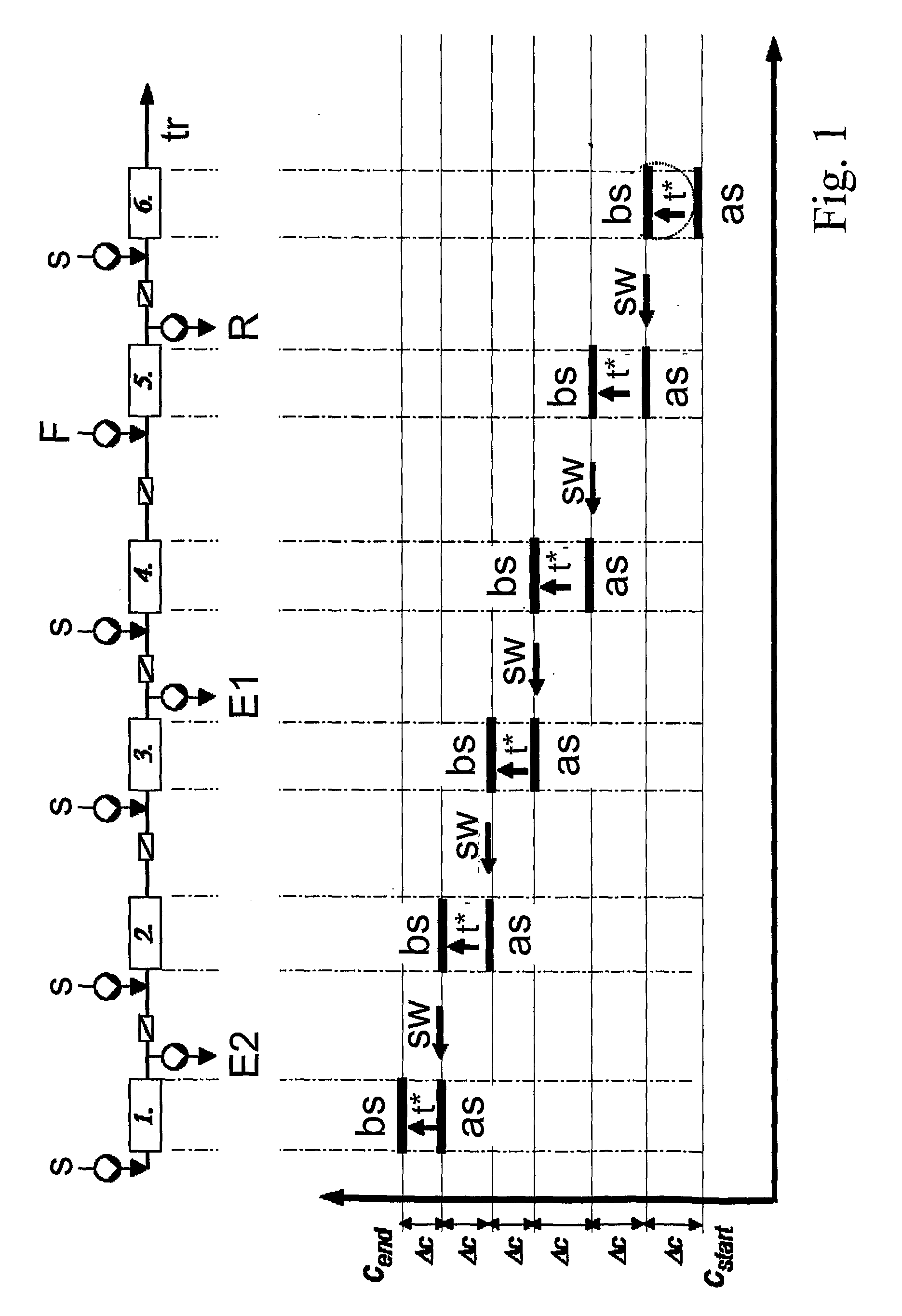
[0015]The gist of the invention is, among other things, the fact that by means of a clever combination of continuous steps or functions and batch steps or functions, which may be carried out sequentially (in a staged manner) or synchronously, i.e. concomitantly, and countercurrent shifting of columns (quasi simulated moving bed), a most efficient purification of an intermediate fraction is possible due to the fact that in the batch steps or positions elution of the desired fraction or of the side fractions can be effected very efficiently, and due to the fact that the continuous steps or positions allow the recycling of fractions.
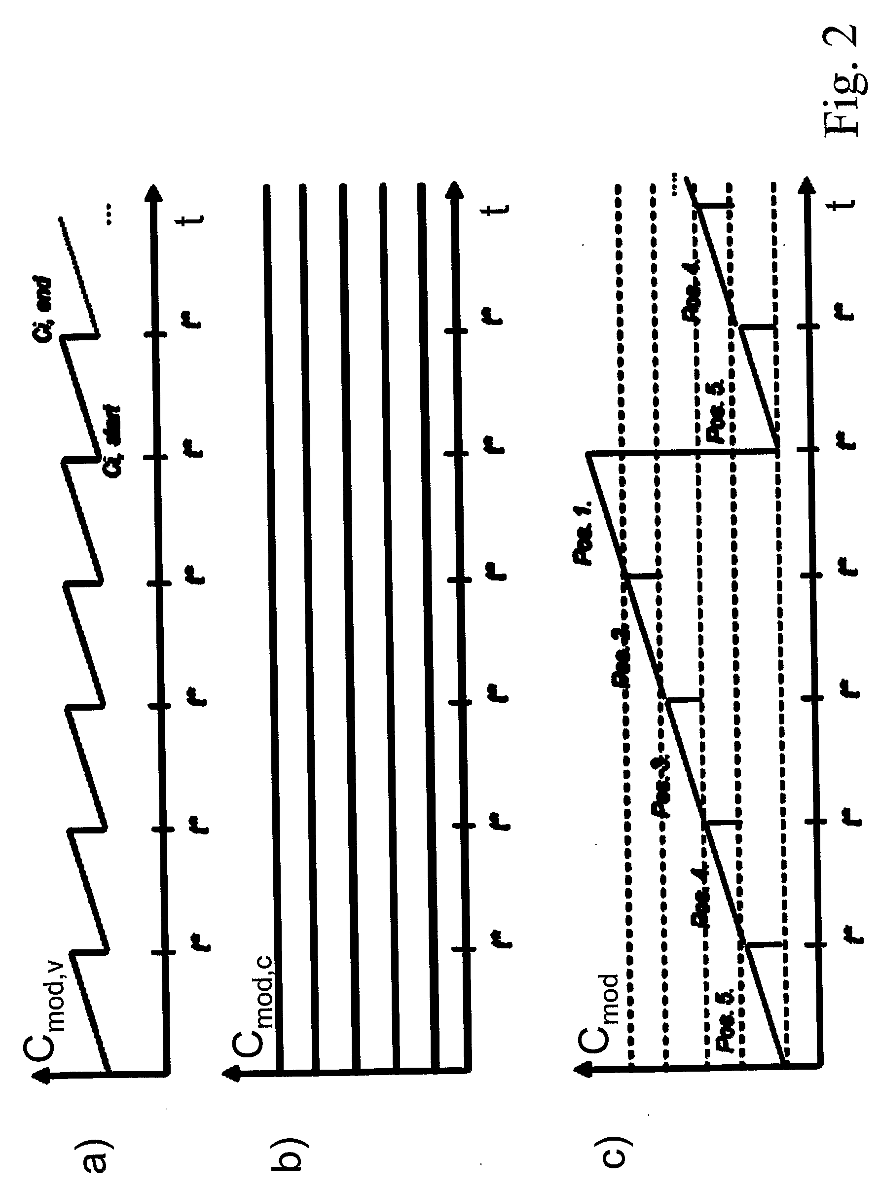
[0020]Instead of solvent concentration gradients (as will be discussed in much detail below) during a switch-time, in SFC pressure gradients are applied, so that the density of the supercritical solvent is adjusted in the proper way to achieve the separation desired. The pressure gradients can be adjusted by pressure controlled valves behind the chromatographic columns. In SFC the system can be operated in closed loop, because it is possible to recycle the solvent. After the supercritical solvent has left the device in section delta (see below), it can be easily reconditioned by changing its pressure and density. So if in the following mention is made of concentration gradients this, in case of a supercritical solvent, is meant to include a corresponding density variation.
[0027]Technically, such a gradient can be implemented most easily if at each solvent inlet solvent with individual constant base concentration of modifier is provided, and if a solvent stream with periodically varying composition (i.e. e.g. modifier concentration), and / or flow-rate is provided to each inlet and mixed with the solvent with individual constant base concentration of modifier to establish the gradient along the system.
[0038]The more complicated the set up for a purification, the more important it becomes to find an easy way of setting up the parameters for such a purification scheme. In the present case this is possible by first running a standard gradient batch chromatogram of the feed and by a simple, straightforward and intuitive analysis of the batch data.

Problems solved by technology

The technique is however rather costly in particular for large scale separation and purification due to high solvent consumption and expensive column material, and it requires an optimal use of the chromatographic equipment to be profitable.
As already mentioned, in particular large scale chromatography is a laborious and expensive technique.
Two staged or sequential SMB would be required to purify a multicomponent mixture with an intermediate desired biomolecule and heavy and light impurities however with the problem that if e.g. in a first stage SMB a first raffinate and a first extract is generated and in a second stage SMB the first extract is separated in a second raffinate (desired product) and a second extract, all undesired constituents which should have been separated in the first stage (and should have ended in the first raffinate) will certainly end up in the second raffinate which in particular for low concentrations of the desired fraction makes such processes useless.

Method used


Image

  • Method and device for chromatographic purification
  • Method and device for chromatographic purification
  • Method and device for chromatographic purification

Examples


experimental verification

Purification of Calcitonin

[0137]The novel process has been experimentally verified with an 8 column open loop system as shown in FIG. 15. Input parameters for the experiment are taken from a simulation. The figure below is equivalent to FIG. 6. The chromatogram as well as the solvent gradient is split into tasks, fulfilled by the four sections α-β-δ. The process is fully analogue to the gradient batch elution, but enables countercurrent recycling of the non pure side-fractions in section δ and between section β and δ.

[0138]The 8 columns inside the four sections have the following tasks:

Section γ: (1 column)[0139]Column 1. wash component C out of the system.

Section β: (1 column)[0140]Column 2. wash out a small valuable amount of B, which is contaminated by C. To recycle B, the liquid outlet stream of column 2. is washed into column 5.

Section α: (1 column)[0141]Column 3. wash out the purified product B. Fresh solvent is used to guarantee the highest possible purity.

Section δ: (5 colum...


PUM


Abstract

A process for continuous or quasi-continuous purification of a multi-component mixture (F) by means of individual chromatographic columns through which the mixture is fed by means of at least one solvent (s), is proposed. The multi-component mixture (F) at least comprises light impurities (A), an intermediate product (B) to be purified and heavy impurities (C), and the columns are grouped into at least four sections (α, β, γ, δ), in which the first section (α) is provided with at least one inlet of solvent (s) and at least one outlet for purified intermediate product (B), such that it washes the purified intermediate product (B) out of the system, but keeps the heavy impurities (C) inside the section (α), the one inlet of solvent (β) and at least one outlet connected to an inlet of the fourth section (δ), such that it washes the intermediate product (B), which is contaminated with heavy impurities (C) into the fourth section (δ) through said outlet, but keeps the pure heavy impurities (C) inside the section (β), the third section (γ) is provided with at least one inlet of solvent (s) and an outlet for heavy impurities (C), such that it washes out the heavy impurities (C) through said outlet and cleans the chromatographic column(s), the fourth section (δ) is provided with at least one inlet to receive output of the outlet of the second section (β) as well as at least one inlet for feeding in the multi-component mixture (F) and at least one outlet for light impurities (A), such that it washes the light impurities (A) out of the system, but keeps the intermediate product (B) inside the section (δ), wherein after or within a switch time (t*) the last column from the first section (α) is moved to the first position of the second section (β), the last column of the second section (β) is moved to the first position of the third section (γ), the last column of the third section (γ) is moved to the first position of the fourth section (δ) and the last column of the fourth section (δ) is moved to become the first column of the first section (α).

Description

TECHNICAL FIELD[0001]The invention relates to the field of multicolumn purification processes and their optimizations.BACKGROUND OF THE INVENTION[0002]Batch chromatography is well known and routinely and preparatively applied in industrial productions. The technique is however rather costly in particular for large scale separation and purification due to high solvent consumption and expensive column material, and it requires an optimal use of the chromatographic equipment to be profitable.[0003]For large scale separations in actual productions continuous processes are much more economic than batch processes. The advantages of a continuous process is for example high yield, less solvent consumption (recovery), less costly fractionation and analyses, better flexibility for the quantities to be purified etc.[0004]One way to realize a continuous chromatographic process is the so called Simulated Moving Bed Process (SMB, for a review see e.g. Markus Juza, Marco Mazzotti and Massimo Morbi...

Claims


Application Information

Patent Timeline
IPC IPC(8): B01D15/18
CPCB01D15/1828G01N30/468B01D15/1864
Inventor AUMANN, LARSMORBIDELLI, MASSIMO
Owner ETH ZZURICH
Learn More