Inert gas etching

a technology of inert gas and etching, which is applied in the field of nanostructure films and patterning methods, can solve the problems of high-temperature sputtering, high-temperature etching, and high-temperature etching

Inactive Publication Date: 2009-02-26
SAMSUNG ELECTRONICS CO LTD
View PDF12 Cites 27 Cited by
  • Summary
  • Abstract
  • Description
  • Claims
  • Application Information

AI Technical Summary

Problems solved by technology

However, ITO can be an inadequate solution for many of the above-mentioned applications (e.g., due to its relatively brittle nature, correspondingly inferior flexibility and abrasion resistance), and the indium component of ITO is rapidly becoming a scarce commodity.
Additionally, ITO deposition usually requires expensive, high-temperature sputtering, which can be incompatible with many device process flows.

Method used


Image

  • Inert gas etching
  • Inert gas etching
  • Inert gas etching

Examples


Embodiment Construction

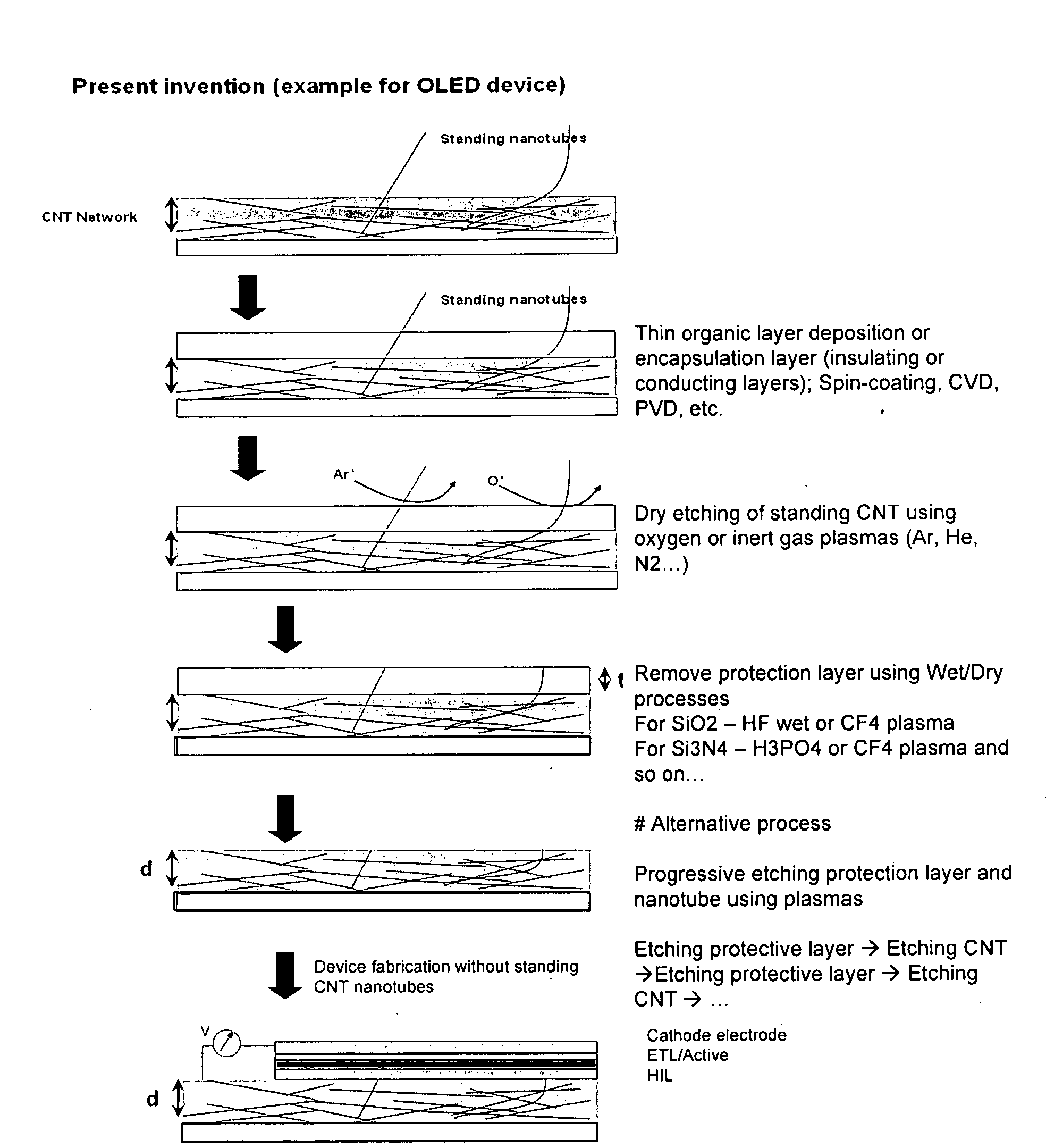
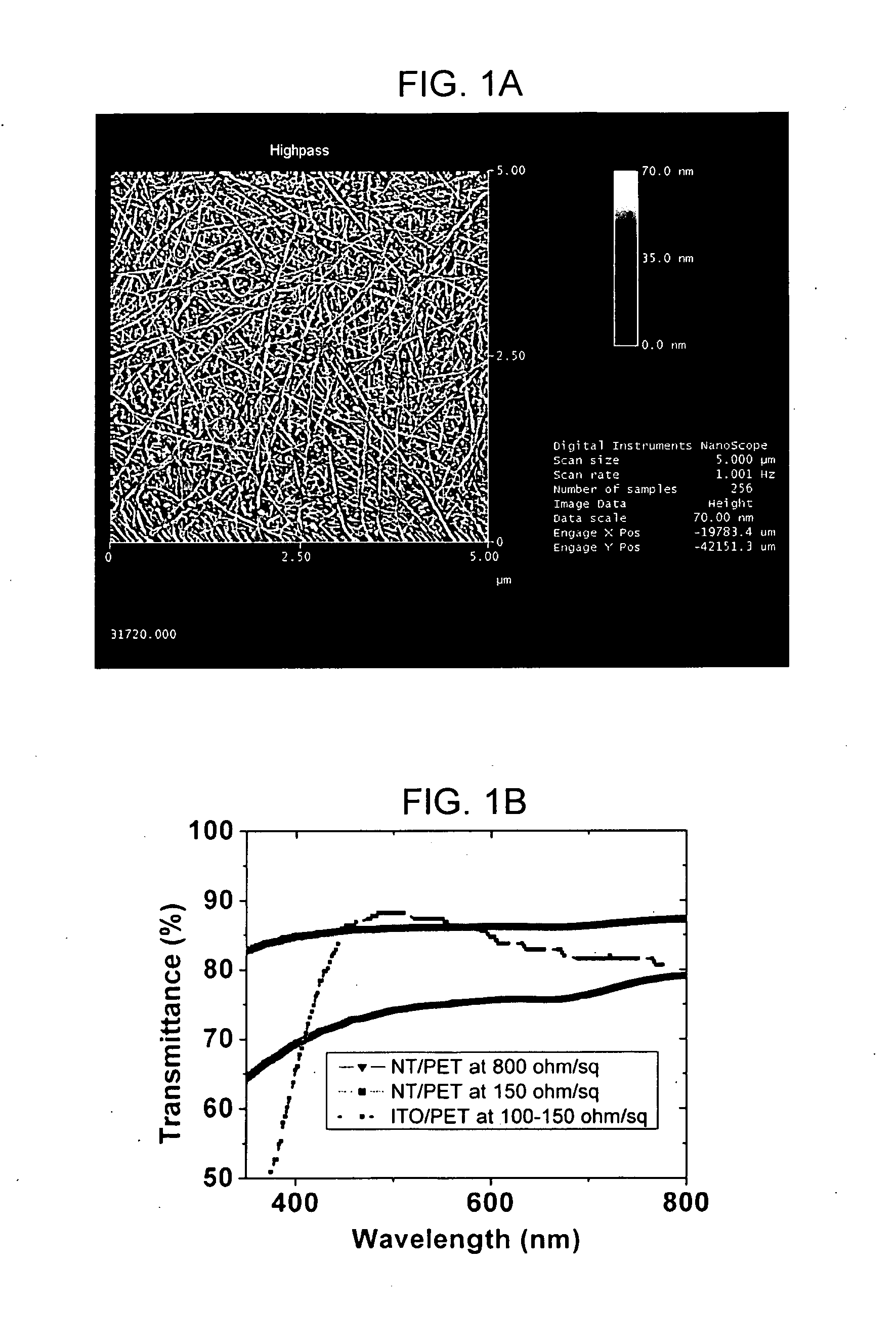
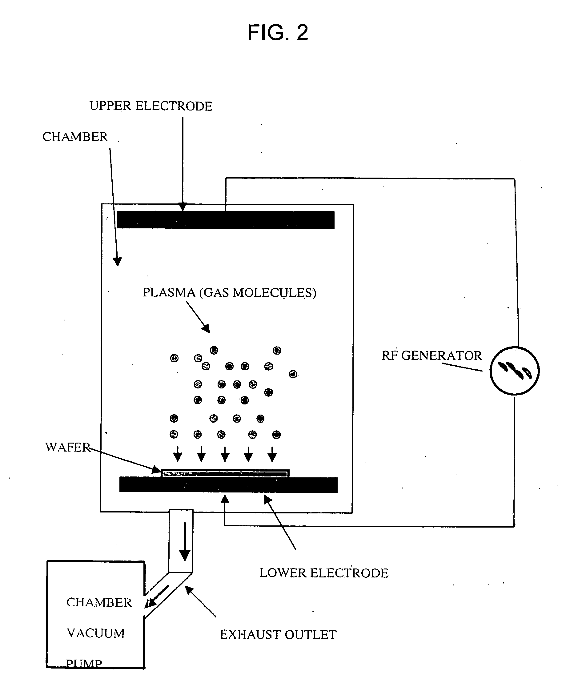
[0017]Referring to FIG. 1, a nanostructure film according to one embodiment of the present invention comprises at least one interconnected network of single-walled carbon nanotubes (SWNTs). Such film may additionally or alternatively comprise other nanotubes (e.g., MWNTs, DWNTs), other fullerenes (e.g., buckyballs), graphene flakes / sheets, and / or nanowires (e.g., metallic (e.g., Ag, Ni, Pt, Au), semiconducting (e.g., InP, Si, GaN), dielectric (e.g., SiO2,TiO2), organic, inorganic).

[0018]Such nanostructure film may further comprise at least one functionalization material bonded to the nanostructure film. For example, a dopant bonded to the nanostructure film may increases the electrical conductivity of the film by increasing carrier concentration. Such dopant may comprise at least one of Iodine (I2), Bromine (Br2), polymer-supported Bromine (Br2), Antimonypentafluride (SbF5), Phosphoruspentachloride (PCl5), Vanadiumoxytrifluride (VOF3), Silver(II)Fluoride (AgF2), 2,1,3-Benzoxadiazole...


PUM

PropertyMeasurementUnit
semi-transparentaaaaaaaaaa
poweraaaaaaaaaa
transparencyaaaaaaaaaa

Abstract

A method of patterning a nanostructure film using a plasma is described. The nanostructure film may substantially comprise carbon and / or carbon nanotubes. The plasma may comprise an inert gas. The plasma may be applied to the nanostructure film at close to atmospheric pressure and room temperature.

Description

FIELD OF THE INVENTION[0001]This application claims priority to U.S. Provisional Patent Application No. 60 / 957,531, filed Aug. 23, 2007 and entitled “INERT GAS ETCHING,” the entire contents of which are incorporated herein by reference.FIELD OF THE INVENTION[0002]The present invention relates generally to nanostructure films, and more specifically to patterning methods thereof.BACKGROUND OF THE INVENTION[0003]Many modern and / or emerging applications require at least one device electrode that has not only high electrical conductivity, but high optical transparency as well. Such applications include, but are not limited to, touch screens (e.g., analog, resistive, 4-wire resistive, 5-wire resistive, surface capacitive, projected capacitive, multi-touch, etc.), displays (e.g., flexible, rigid, electro-phoretic, electro-luminescent, electrochromatic, liquid crystal (LCD), plasma (PDP), organic light emitting diode (OLED), etc.), solar cells (e.g., silicon (amorphous, protocrystalline, na...

Claims


Application Information

Patent Timeline
Patent Type & Authority Applications(United States)
IPC IPC(8): H01B13/00
CPCB82Y10/00H01L21/32131H01L21/32136H01L51/0049H01L51/002H01L51/0048H01L51/0003H10K71/12H10K71/30H10K85/221H10K85/225
Inventor PARK, YOUNGBAEHU, LIANGBING
Owner SAMSUNG ELECTRONICS CO LTD
Why Eureka
Try Eureka