Means for conveying material

a technology of conveying material and conveying equipment, which is applied in the direction of lighting and heating equipment, charge manipulation, furnaces, etc., can solve the problems of high energy consumption, high production cost, and frequent maintenance of conveyor systems, and achieves simple structure, improved gaseous fluid effectiveness, and limited maintenance

Inactive Publication Date: 2009-02-26
DANIELI & C OFF MEC SPA
View PDF6 Cites 2 Cited by
  • Summary
  • Abstract
  • Description
  • Claims
  • Application Information

AI Technical Summary

Benefits of technology

[0015]The device according to the invention advantageously comprises, inside the conveyor trough or tunnel, equalizing baffles that define accumulation cells and considerably improve the effectiveness of the gaseous fluids that are forced through the granular bed, for instance to prevent oxidation of the hot DRI or off-g...

Problems solved by technology

The separation of the reduction and steelmaking plants, by means of a buffer, is necessary because the electric arc furnace operates on a batch cycle basis, whereas direct reduction plants operate continuously and it is neither possible nor advantageous to stop the flow in the reduction furnace according to the amount of DRI that is used.
Conventional conveyor systems, for example belt, bucket or chain conveyors, involve high production costs and require frequent maintenance.
Furthermore, they use a considerable amount of electrical power, resulting in high energy consumption.
Finally, sai...

Method used


Image

  • Means for conveying material
  • Means for conveying material
  • Means for conveying material

Examples


Embodiment Construction

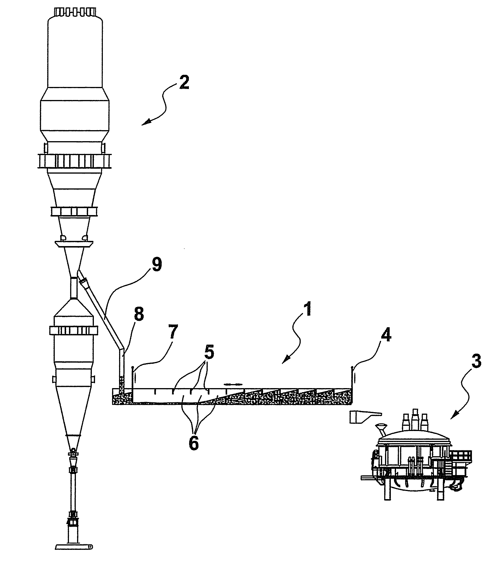
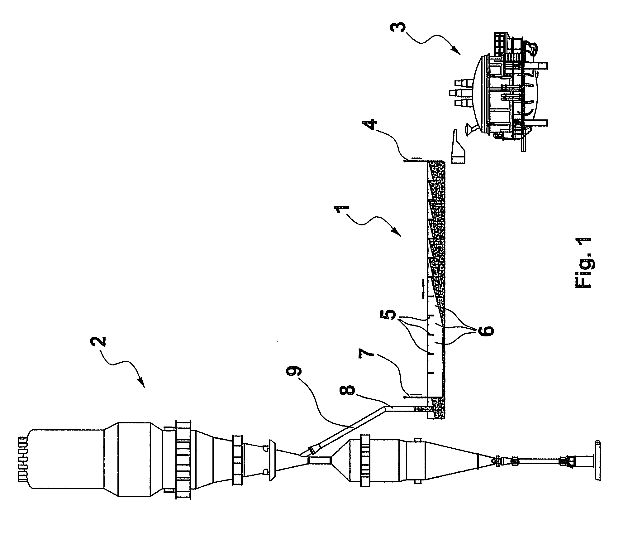
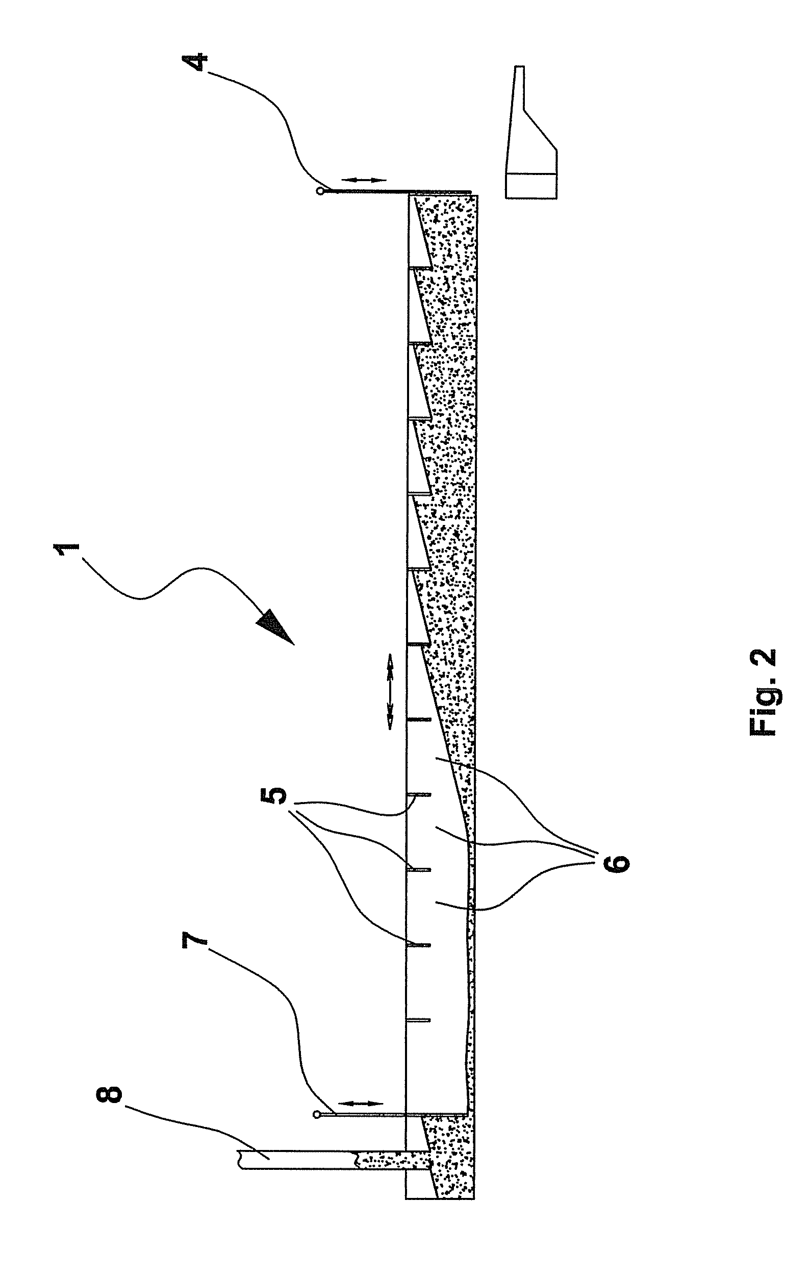
[0022]With reference to the drawings, which are provided purely by way of example and are not limitative, a conveyor means is illustrated comprising a horizontal, or slightly slanting vibrating conveyor 1, that directly links the reactor 2 or shaft furnace with the electric arc furnace 3 and also acts as a buffer for the hot material being conveyed. The vibratory motion may be provided to the conveyor 1 by means of an eccentric-mass vibration generator, or by means of magnetic devices, or more generally, by any other system suitable for this purpose.

[0023]When the electric arc furnace 3 or EAF, which stands for “Electric Arc Furnace”, is deactivated in order to tap the molten steel, the vibrating conveyor 1 continues to run but is closed at the discharge end or outlet by means of a first mobile dam or sluice gate 4, which slides vertically, in order to interrupt the flow of material into the furnace. With the discharge outlet closed, the vibratory motion causes a natural build-up of...


PUM

PropertyMeasurementUnit
Flow rateaaaaaaaaaa
Distanceaaaaaaaaaa

Abstract

Means for conveying hot granular material from a loading zone to an arc melting furnace (3), comprising a horizontal trough (1), trough vibration generators that cause the granular material to move along the trough, a sluice gate (4) to regulate the material flow in the discharge zone and a sluice gate to regulate the material flow in correspondence with the loading zone. Separating baffles (5) are arranged inside the conveyor trough defining cells in which the granular material accumulates and considerably improving the effectiveness of the action of the gases that are forced through the granular bed, for instance to prevent oxidation of the hot DRI or to perform an additional reduction process.

Description

FIELD OF THE INVENTION[0001]The present invention relates to a means for conveying material, in particular a means suitable, for example, for conveying materials of different types and in different forms, such as granular materials or materials in the form of lumps or pellets, inside a production or processing plant.PRIOR ART[0002]Various types of conveyor systems are known in the prior art. One important application for these systems is that of conveying hot pre-reduced iron, also known as DRI or “Direct Reduced Iron”, from a direct reduction furnace, towards an electric arc melting furnace in a metallurgical plant, in particular a steelworks.[0003]Transporting the DRI directly to the electric arc furnace is clearly advantageous but involves a number of requirements, namely:[0004]the connection between the two furnaces must be rendered inert, as the metal will re-oxidize when exposed to atmospheric air and humidity with a significant loss of metallization;[0005]the reduction and st...

Claims


Application Information

Patent Timeline
IPC IPC(8): C22B9/21B65G27/00
CPCB65G47/19C21C5/527F27D3/0033F27D3/0025F27B3/183Y02P10/20
Inventor VRECH, ARBENOPOLONI, ALFREDO
Owner DANIELI & C OFF MEC SPA
Why Eureka
Try Eureka