
Optical recording medium and method of recording visible information

a recording medium and optical recording technology, applied in the field of optical recording mediums, can solve the problems of low contrast and lack of visibility, difficult to form visible images of high contrast with dyes employed on the (digital) information recording surface of a conventional optical disk, etc., to achieve excellent toughness, high contrast, and excellent visibility.

Inactive Publication Date: 2009-03-05
FUJIFILM CORP
View PDF7 Cites 12 Cited by
  • Summary
  • Abstract
  • Description
  • Claims
  • Application Information

AI Technical Summary

Benefits of technology

[0012]An aspect of the present invention provides for an optical recording medium capable of recording visible information with high contrast and excellent visibility, and more particularly, an optical recording medium affording excellent toughness of recorded images, permitting the recording of visible information with high contrast and excellent visibility by the same laser beam that is employed to record information on the information recording layer, as well as a method for recording visible information.
[0040]According to the present invention, an optical recording medium capable of recording visible information with high contrast and excellent visibility can be provided. In addition, since a visible information recording layer comprising the aforementioned combination of dyes is highly stable over time, it is possible to provide an optical recording medium affording good storage properties. Further, the aforementioned combination of dyes is suited to a system for forming images by a new recording method differing from common digital data recording, and permits the formation of visible information with high contrast, sharpness, and excellent resistance to light in such a system.

Problems solved by technology

However, the visible image that is formed by a high-powered gas laser such as the carbon dioxide gas laser employed in the method described in Japanese Unexamined Patent Publication (KOKAI) Heisei No, 11-66617 is of low contrast and lacks visibility.
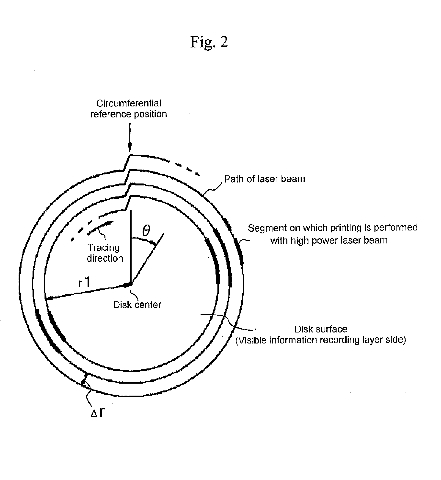
In the method for recording images described in Japanese Unexamined Patent Publication (KOKAI) No. 2002-203321, since the laser beam is directed onto the label surface along a path differing from that used in normal digital data recording, it is difficult to form visible images of high contrast with the dyes employed on the (digital) information recording surface of a conventional optical disk.
Further, the dyes employed on the image display surface tend to fade during storage and with exposure to light; there is thus a problem in that the contrast of the image gradually decreases over time, precluding the long-term maintenance of visibility.

Method used


Image

  • Optical recording medium and method of recording visible information
  • Optical recording medium and method of recording visible information
  • Optical recording medium and method of recording visible information

Examples


example 1

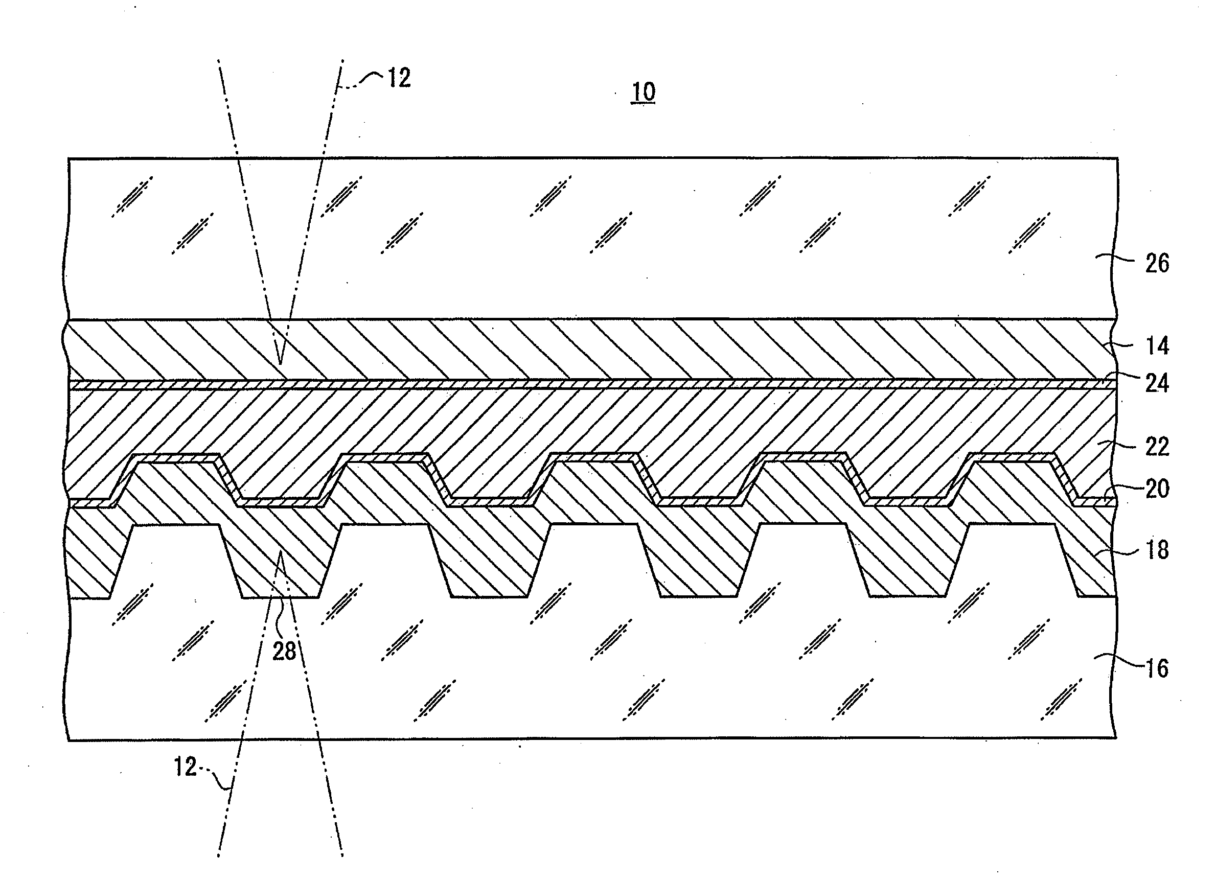
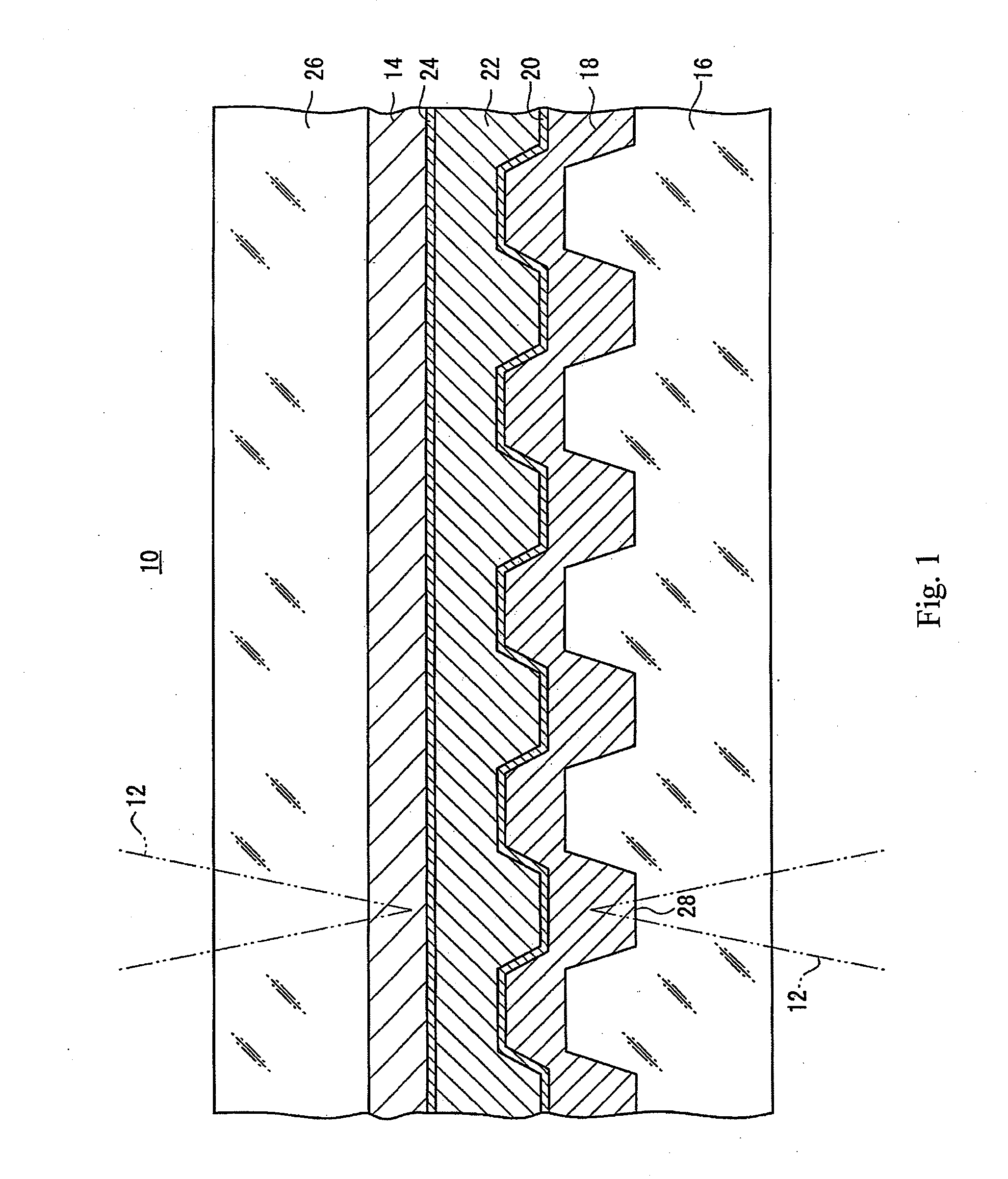
[0300]Example 1 of the optical information recording medium had the layer structure shown in FIG. 1. It was a DVD-R type optical recording medium comprised of two bonded disks. The method of manufacturing the optical recording medium of Example 1 will be described below.

[0301]A first support 16 that was 0.6 mm in thickness, 120 mm in diameter, and had spiral (helical) grooves (130 nm deep, 300 mm in width, with a track pitch of 0.74 micrometers) was formed out of polycarbonate resin by injection molding.

[0302]Subsequently, a coating liquid was prepared by dissolving 1.5 g each of the two oxonol dyes indicated below in 100 mL of 2,2,3,3-tetrafluoro-1-propanol. The coating liquid was coated by spin coating to the surface of first support 16 on which pregrooves 28 had been formed, yielding a recording layer 18 that was 80 micrometers thick.

[0303]Next, silver was sputtered onto recording layer 18 to form a first reflective layer 20 that was 120 nm in thickness, UV-curing resin (SD318, m...


PUM


Abstract

The optical recording medium comprises a visible information recording layer comprising at least two dyes of the following dyes.Ra1 to Rb3 each independently denote a hydrogen atom or a monovalent substituent, Ra2 and Ra3 may bond together to form a five to seven-membered heterocyclic ring, A denotes a substituted or unsubstituted aliphatic group, substituted or unsubstituted aryl group, or substituted or unsubstituted heterocyclic group, n denotes 0, 1, 2, or 3.In general formula (II), Rα1 to Rα8 and Rβ1 to Rβ8 each independently denote a hydrogen atom or a monovalent substituent, M denotes two hydrogen atoms, a metal, a metal oxide, or a metal having a ligand.A1═N—B1  General formula (III)A1 denotes a substituted or unsubstituted heterocyclic group, a substituted aliphatic group, or a substituted or unsubstituted carbocyclic group, and B1 denotes a substituted or unsubstituted heterocyclic group or a substituted or unsubstituted aryl group.

Description

CROSS-REFERENCE TO RELATED APPLICATIONS[0001]This application claims the benefit of priority under 35 USC 119 to Japanese Patent Application No. 2007-014559 filed on Jan. 25, 2007, which is expressly incorporated herein by reference in its entirety.BACKGROUND OF THE INVENTION[0002]1. Field of the Invention[0003]The present invention relates to an optical recording medium, and more particularly, to an optical recording medium having a recording layer for recording music data and the like, and a visible information recording layer for recording visible information to identify recorded data. The present invention further relates to a method of recording visible information on the optical recording medium.[0004]2. Discussion of the Background[0005]Optical information recording media (optical disks) on which information can be recorded once by means of a laser beam are known. Such optical disks include recordable CDs (known as “CD-Rs”) and recordable digital versatile disks (known as “DV...

Claims


Application Information

Patent Timeline
IPC IPC(8): B41J2/435B32B33/00B32B3/00G11B7/24027G11B7/24035G11B7/24094G11B7/24097G11B7/246G11B7/249G11B7/257
CPCB41M5/28G11B2007/25718G11B7/0037G11B7/2433G11B7/246G11B7/2467G11B7/2472G11B7/2478G11B7/248G11B7/249G11B7/256G11B7/257G11B7/258G11B2007/24612G11B2007/2571G11B2007/25713G11B2007/25715B41M5/286
Inventor SETO, NOBUOSHIBATA, MICHIHIRO
Owner FUJIFILM CORP
Learn More