Plasma treatment apparatus, and substrate heating mechanism to be used in the apparatus

Inactive Publication Date: 2009-03-12
TOKYO ELECTRON LTD
View PDF9 Cites 25 Cited by
  • Summary
  • Abstract
  • Description
  • Claims
  • Application Information

AI Technical Summary

Benefits of technology

[0022]According to the present invention, the heating element and electrode are made of SiC, so that the temperature of the target substrate can be set at 800° C. or more, and a plasma process can be performed on the target substrate at a predetermined high temperature. Further, the substrate table 7 having a heating function has a structure that prevents contaminants from being diffused from inside when a plasma process is performed at a high temperature, so that the plasma process can be performed within a clean atmosphere. Consequently, a film with good propert

Problems solved by technology

However, where the substrate table 203 includes an AlN heater, 700° C. is the upper limit of the heater in heating itself, and so the target substrate W cannot be heated to a temperature of 700° C. or more.
There is a stainless steel heater that can heat to 800° C., but stainless steel heaters may cause contamination by heavy metals, such as Fe and Cr, contained in th

Method used


Image

  • Plasma treatment apparatus, and substrate heating mechanism to be used in the apparatus
  • Plasma treatment apparatus, and substrate heating mechanism to be used in the apparatus
  • Plasma treatment apparatus, and substrate heating mechanism to be used in the apparatus

Examples


Embodiment Construction

[0039]An embodiment of the present invention will now be described with reference to the accompanying drawings.

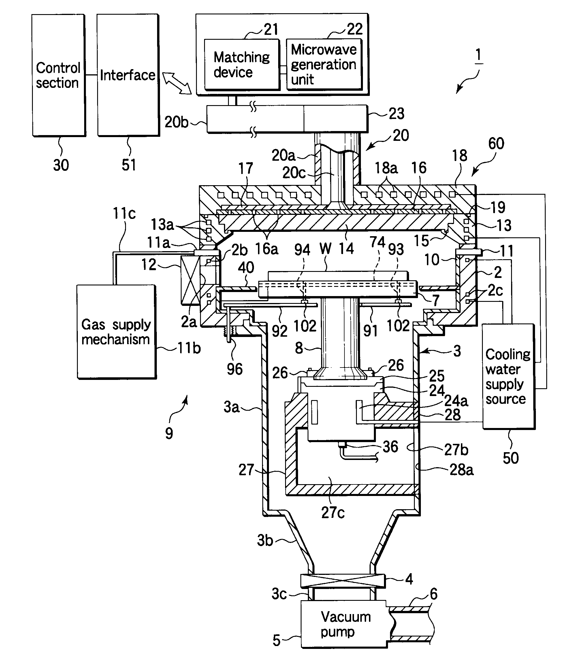
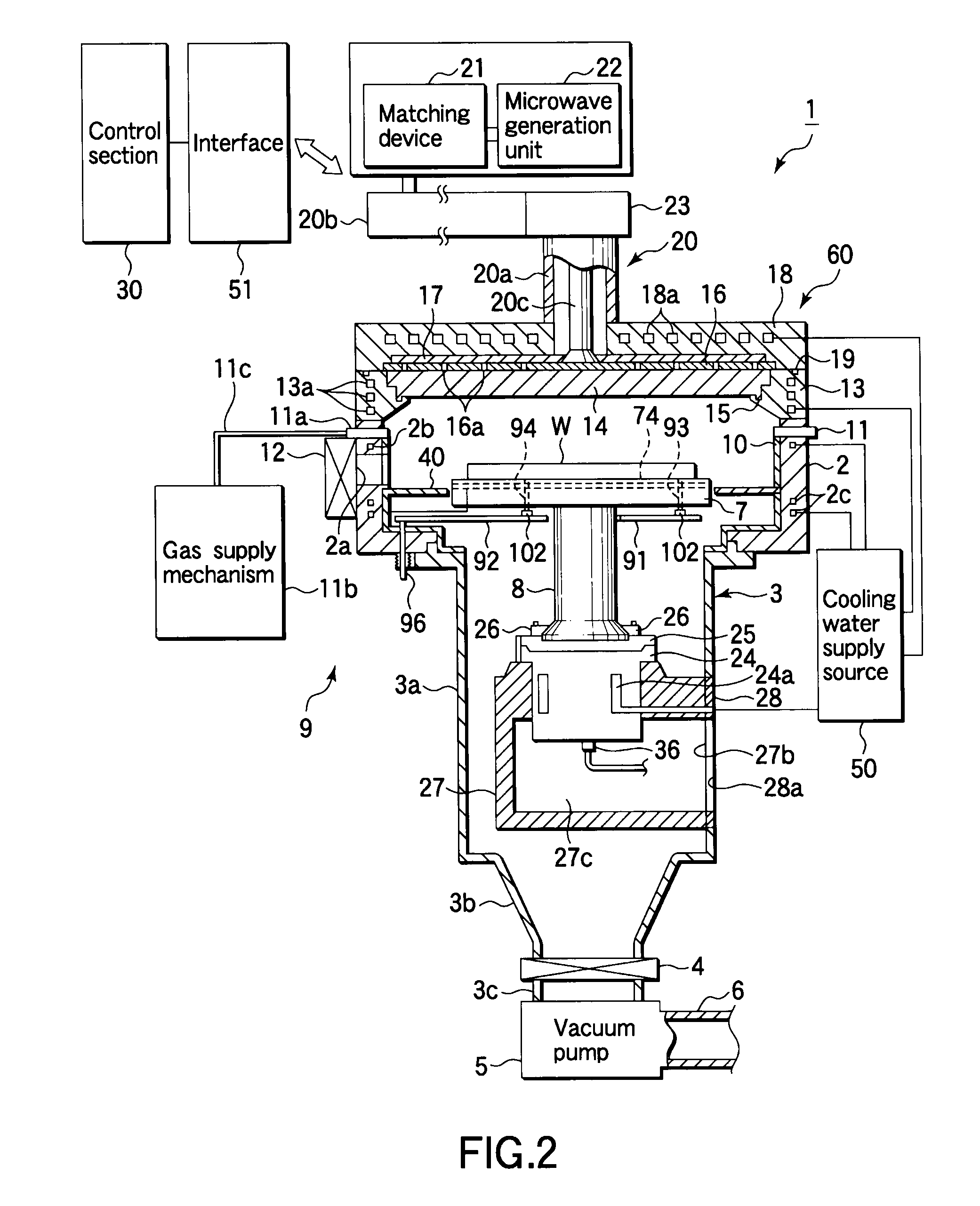
[0040]FIG. 2 is a sectional view schematically showing a microwave plasma processing apparatus according to an embodiment of the present invention. In FIG. 2, reference symbol 1 indicates a microwave plasma processing apparatus.

[0041]This microwave plasma processing apparatus 1 includes an airtight chamber 2 having an essentially cylindrical shape. The essentially cylindrical shape of the chamber 2 is made of a metal, such as Al. The bottom of the chamber 2 has an opening portion at the center, and an exhaust pipe 3 is disposed continuously to the bottom. The exhaust pipe 3 comprises an upper exhaust pipe 3a having essentially the same diameter as the opening portion, a tapered portion 3b with a diameter gradually decreasing downward, and an lower exhaust pipe 3c connected to the tapered portion 3b through a flow passage adjusting valve 4. The lower end of the lower exhaust...


PUM

PropertyMeasurementUnit
Diameteraaaaaaaaaa
Radiant heataaaaaaaaaa
Electrical conductoraaaaaaaaaa

Abstract

A plasma processing apparatus includes a chamber configured to accommodate a target substrate; a plasma generation mechanism configured to generate plasma inside the chamber; a process gas supply mechanism configured to supply a process gas into the chamber; an exhaust mechanism connected to the chamber to exhaust gas from inside the chamber; a table configured to place the target substrate thereon inside the chamber, the table including a table main body and a heating element disposed in the main body to heat the substrate; a support portion that supports the substrate table; a fixing member that fixes the support portion to the chamber; and an electrode configured to supply a power to the heating element, wherein the heating element and the electrode are made of an SiC-containing material, the electrode is fixed to the fixing member, extends through the support portion, and is connected to the heating element at a distal end, and an electrode sheath member made of a quartz-containing insulative material envelops the electrode except for the distal end, and extends through a portion of the substrate table below the heating element, the support portion, and the fixing member.

Description

TECHNICAL FIELD[0001]The present invention relates to a plasma processing apparatus for performing a plasma process on a target substrate, such as a semiconductor substrate, and a substrate heating mechanism used for the plasma processing apparatus.BACKGROUND ART[0002]There are plasma processing apparatuses of various plasma excitation types used for manufacturing semiconductor devices, liquid crystal display devices, and so forth. For example, in general, RF (Radio Frequency) excited plasma processing apparatuses using RF of 13.56 MHz and microwave plasma processing apparatuses using microwaves of 2.45 GHz are employed. As compared with RF excited plasma processing apparatuses, microwave plasma processing apparatuses provide higher density plasma and lower plasma ion energy, and thus are advantageous such that members inside the processing apparatuses and target substrates can be less damaged and less contaminated.[0003]Due to such advantages, studies have been made to apply microw...

Claims


Application Information

Patent Timeline
IPC IPC(8): B23K9/00
CPCH01J37/20H01J37/32192H01J2237/2001H01L21/02238H01L21/68742H01L21/31662H01L21/67069H01L21/67103H01L21/02252H01L21/683H05H1/46
Inventor YAMASHITA, JUN
Owner TOKYO ELECTRON LTD
Why Eureka
Try Eureka