Laser Light Source and Optical Device

a laser light source and optical device technology, applied in semiconductor lasers, active medium materials, instruments, etc., can solve the problems of requiring a cooling device and a large apparatus construction including a cooling device, and achieve high output power, reduce the coherence of laser light sources, and generate monochrome light high-efficiency

Inactive Publication Date: 2009-03-12
PANASONIC CORP
View PDF14 Cites 51 Cited by
  • Summary
  • Abstract
  • Description
  • Claims
  • Application Information

AI Technical Summary

Benefits of technology

[0082]According to the laser light source of the present invention, the laser light source comprises a laser medium, a pump light source comprising a semiconductor laser, and a multi-mode means for changing at least either a longitudinal mode or a transverse mode of laser oscillation from the laser medium into a multi-mode. Therefore, highly-efficient monochrome light generation and a reduction in coherence of the laser light source can be realized. Further, by applying this laser light source into an optical device, a small, high output power, and high image quality optical device with no speckle noises can be realized.
[0083]Further, by using a laser medium which is doped with a doping material such as Pr3+, a plurality of laser beams such as red, green, and blue in accordance with the doping material can be generated.
[0084]Furthermore, according to the laser light source of the present i

Problems solved by technology

However, since energy conversion efficiencies of these gas lasers are quite low as a

Method used


Image

  • Laser Light Source and Optical Device
  • Laser Light Source and Optical Device
  • Laser Light Source and Optical Device

Examples


first embodiment

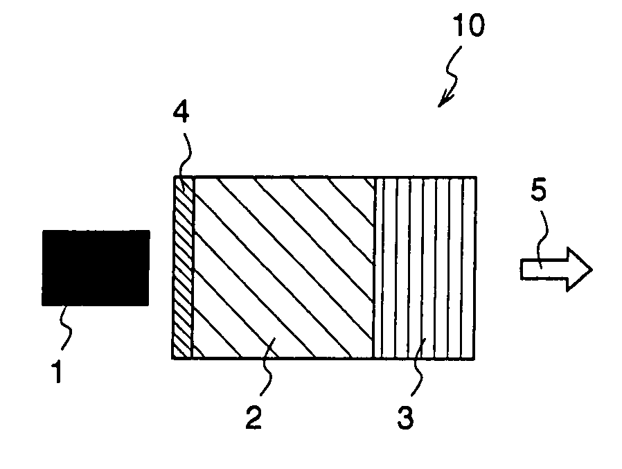
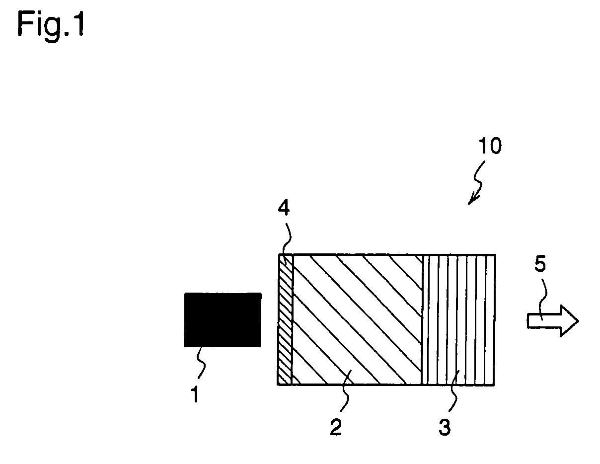
[0157]FIG. 1 is a diagram illustrating a construction of a laser light source according to this first embodiment. Reference numeral 1 denotes a gallium nitride (GaN) semiconductor laser, reference numeral 2 denotes a laser medium which is doped with trivalent praseodymium ion (Pr3), reference numeral 3 denotes a reflector, reference numeral 4 denotes a multilayer mirror, reference numeral 10 denotes a laser light source, and reference numeral 5 denotes output light from the laser light source.

[0158]The GaN laser 1 is a wide-stripe semiconductor laser, and has an oscillation wavelength in the vicinity of 440 nm, and output power thereof ranges from 500 mW to few watts. The multilayer mirror 4 transmits a wavelength of 440 nm and reflects a wavelength in the vicinity of 530 nm. The reflector 3 is a grating mirror having a narrow-band reflection characteristic in the vicinity of 530 nm. The laser medium 2 has an absorption characteristic in the vicinity of 440 nm and an oscillation cha...

second embodiment

[0208]In this second embodiment, description will be given of a laser light source using a doped fiber. FIG. 9(a) is a diagram illustrating a construction of a laser light source according to this second embodiment. Reference numeral 1 denotes a GaN semiconductor laser, reference numeral 72 denotes a double-clad fiber whose core is doped with Pr3+, reference numeral 73 denotes a grating fiber, reference numeral 74 denotes a multilayer mirror, reference numeral 70a denotes a laser light source, and reference numeral 75a denotes output light from the laser light source.

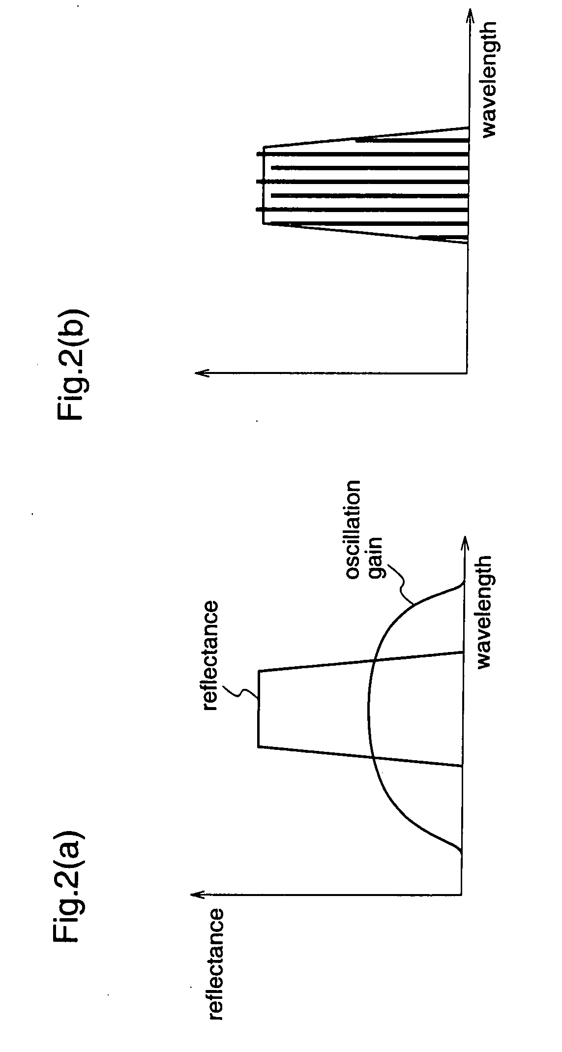
[0209]The GaN laser 1 is a wide stripe semiconductor laser as similarly in the first embodiment, and has a wavelength in the vicinity of 440 nm, and output power thereof ranges from 500 mW to few watts. The multilayer mirror 74 transmits a wavelength of 440 nm and reflects a wavelength in the vicinity of 530 nm. As shown in FIG. 2(a), a grating having a narrow-band reflection characteristic whose wavelength range is bro...

third embodiment

[0227]In this third embodiment, description will given of a construction in which output light is changed into a multi-mode by providing a plurality of cores in a single fiber

[0228]FIG. 12(a) is a diagram illustrating a construction of a light source according to this third embodiment, and figure 12(b) is a diagram illustrating a cross-sectional view of the doped fiber.

[0229]In FIG. 12, reference numeral 1 denotes a GaN system semiconductor laser, reference numeral 102 denotes a double-clad doped fiber which is doped with trivalent praseodymium (Pr3+), reference numeral 103 denotes a grating, reference numeral 104 denotes a multilayer mirror 104, reference numeral 100 denotes a laser light source, and reference numeral 105 denotes output light from the light source.

[0230]The core of the doped fiber 102 comprises a plurality of cores 106a-106c and a clad 107. The multilayer mirror 104 is a dichroic mirror which transmits light of less than 500 nm and reflects light of more than 500 n...


PUM


Abstract

A laser light source is provided with a pump light source (1) comprising a semiconductor laser, a solid laser medium (2) which is excited by the semiconductor laser, and multi-mode means for changing at least either a longitudinal mode or a transverse mode of laser oscillation of the solid laser. The oscillation light of the laser medium excited by the light outputted from the pump light source is changed by the multi-mode means into output light (5) having a plurality of oscillation spectra and is outputted, thereby a small, high power, and highly efficient low coherent light source can be realized, and a laser light source having reduced speckle noises can be provided.

Description

TECHNICAL FIELD[0001]The present invention relates to a laser light source using a wavelength conversion element and an optical device using the light source.BACKGROUND ART[0002]In recent years, a laser display apparatus using laser light sources of three colors, i.e., red, green, and blue (hereinafter referred to as “RGB lasers”) has been proposed. Since the laser display apparatus employing the RGB lasers is capable of realizing monochromacy and a broad color representation range of laser, a color display of highly vivid is enabled.[0003]To realize a large-screen display apparatus using RGB lasers, a laser light source of several watts is needed. As means for realizing such laser light source, a high output power Ar laser or Kr laser has been conventionally used. However, since energy conversion efficiencies of these gas lasers are quite low as about 0.1%, a large-scale apparatus construction including a cooling device is needed.[0004]In order to solve this problem, light generati...

Claims


Application Information

Patent Timeline
IPC IPC(8): H01S3/30G02B6/02
CPCH01S3/0602H01S3/0627H01S3/09415H01S3/113H01S5/32341H01S3/0675H01S3/094003H01S5/146H01S3/1613
Inventor MIZUUCHI, KIMINORIYAMAMOTO, KAZUHISA
Owner PANASONIC CORP
Why Eureka
Try Eureka