Directional silicon condenser microphone having additional back chamber

Inactive Publication Date: 2009-03-19
BSE CO LTD
View PDF8 Cites 25 Cited by
  • Summary
  • Abstract
  • Description
  • Claims
  • Application Information

AI Technical Summary

Benefits of technology

[0009]As described above, the present invention includes a chamber case for forming an additional back chamber under a MEMS chip in order to increase a back chamber space of the MEMS chip, thereby improving sensitivity and noise problems such as a THD (Total Harmonic Distortion). In addition, the directional silicon microphone in accordance with the present invention may be mounted on a main PCB via various methods. Therefore,

Problems solved by technology

Therefore, a mountin

Method used


Image

  • Directional silicon condenser microphone having additional back chamber
  • Directional silicon condenser microphone having additional back chamber
  • Directional silicon condenser microphone having additional back chamber

Examples


Embodiment Construction

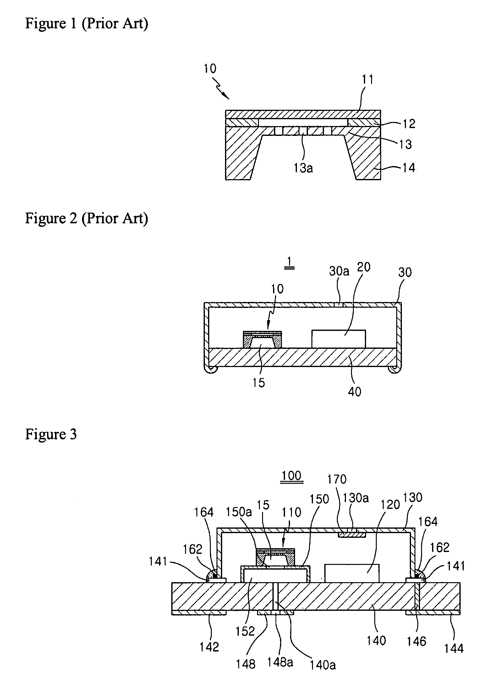
[0018]The above-described objects and other objects and characteristics and advantages of the present invention will now be described in detail with reference to the accompanied drawings.

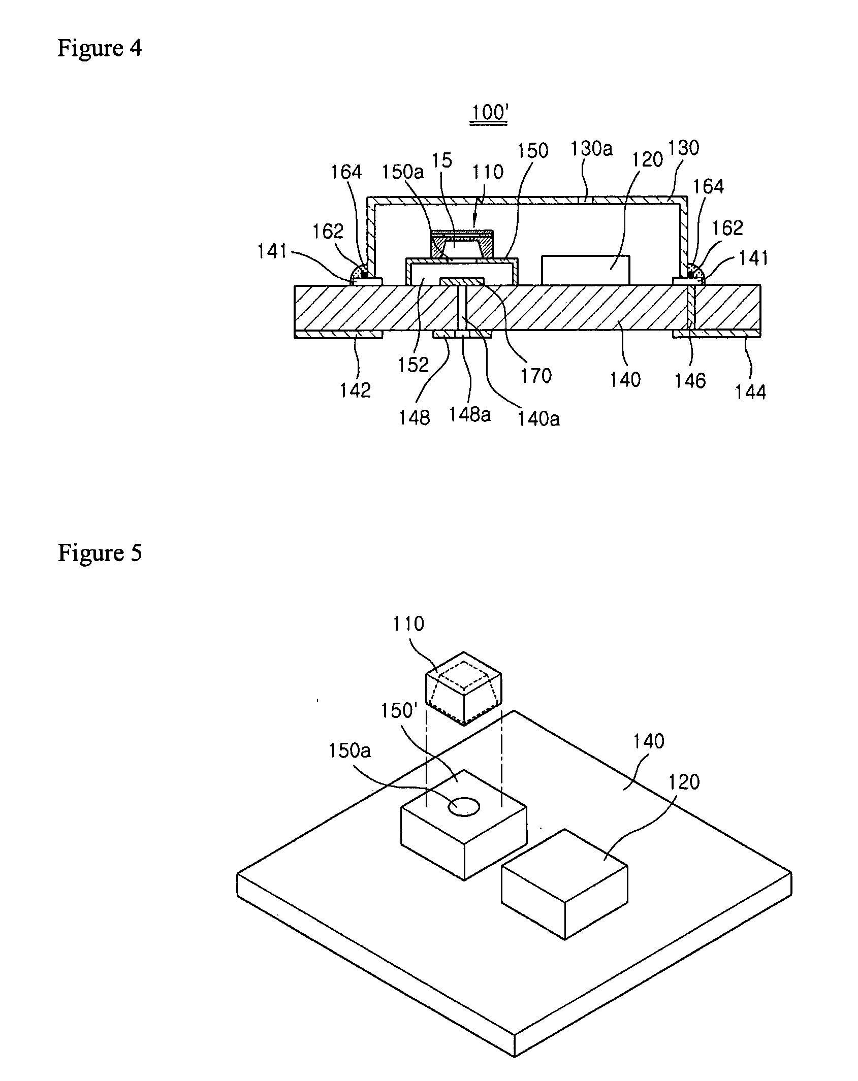
[0019]Typically, the direction condenser microphone includes an acoustic delay device. Embodiments of the present invention will be described by dividing into two examples, an example wherein the acoustic delay device is mounted at a front sound hole of a case for passing through a front sound and an example wherein the acoustic delay device is mounted at a rear sound hole of a PCB for passing through a rear sound.

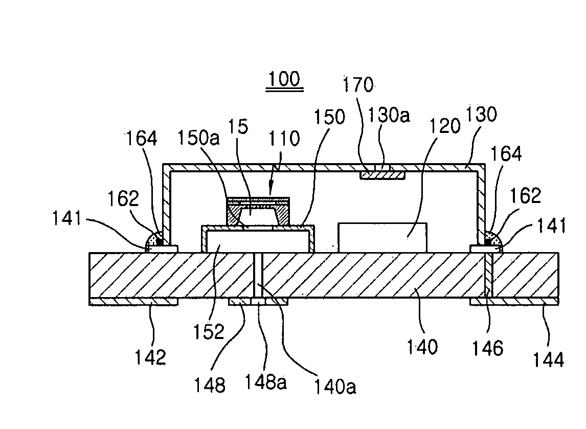
[0020]FIG. 3 is a lateral cross-sectional view illustrating a directional silicon condenser microphone having an additional back chamber in accordance with a first embodiment of the present invention, wherein an acoustic delay device 170 is installed at a front sound hole 130a of the case for passing through the front sound.

[0021]Referring to FIG. 3, the directional silicon condenser micro...


PUM


Abstract

A directional silicon condenser microphone having an additional back chamber is disclosed. The directional silicon condenser microphone comprises a case having a front sound hole for passing through a front sound; a acoustic delay device for delaying a phase of a sound; a substrate including a chamber case, a MEMS chip having an additional back chamber formed by the chamber case, an ASIC chip for operating the MEMS chip, a conductive pattern for bonding the substrate to the case, and a rear sound hole for passing through a rear sound; a fixing means for fixing the case to the substrate; and an adhesive for bonding the case and the substrate, wherein the adhesive is applied to an entirety of a bonding surface of the case and the substrate fixed by the fixing means.

Description

TECHNICAL FIELD[0001]The present invention relates to a condenser microphone, and more particularly to a directional silicon condenser microphone having an additional back chamber.BACKGROUND ART[0002]Generally, a condenser microphone widely used in a mobile communication terminal and an audio system comprises a voltage bias element, a pair of a diaphragm and backplate for constituting a capacitor C varying according to a sound pressure, and a JFET (Junction Field Effect Transistor) for buffering an output signal. The conventional condenser microphone is assembled by sequentially inserting a vibrating plate, a spacer ring, an insulation ring, a backplate and a conductive ring in a case, and finally inserting a PCB and curling an end portion of the case toward the PCB.[0003]Recently, a semiconductor processing technique using micromachining is proposed as a technique for integrating a microscopic device. A MEMS (Micro Electro Mechanical System) employs a semiconductor manufacturing pr...

Claims


Application Information

Patent Timeline
IPC IPC(8): H04R11/04
CPCH04R19/016H04R1/02H04R19/04H04R2201/003H04R2201/02
Inventor SONG, CHUNG DAM
Owner BSE CO LTD
Why Eureka
Try Eureka