Microdrop ablumenal coating system and method

a microdrop and ablumenal technology, applied in the field of coating medical devices, can solve the problems of affecting the kinetic release rate of coatings with embedded drug particles, low deposition efficiency of conventional gas-assist methods delivered by high-speed gas streams, and waste of remaining 95% of coating solution, etc., to achieve the effect of steady flow of microdrops

Inactive Publication Date: 2009-03-19
BOSTON SCI SCIMED INC
View PDF17 Cites 8 Cited by
  • Summary
  • Abstract
  • Description
  • Claims
  • Application Information

AI Technical Summary

Benefits of technology

[0014]In an embodiment, a waste tray may be used. In such an embodiment, the microdrop source may produce a steady, constant-frequency series of coating microdrops. When a scanner indicates that the microdrop source and electrodes are not positioned over a portion of the device that is to be coated, or that the microdrop path cannot be altered sufficiently to direct the microdrop onto a desired area of the medical device, the electric field created by the control electrodes may be adjusted to direct generated microdrops into the waste tray. This may allow the system to coat only desired portions of the medical device while maintaining a steady flow of microdrops. Coating collected in the waste tray may be reused, such as by returning the collected coating to the microdrop source, or it may be discarded.

Problems solved by technology

However, conventional gas-assist coating methods have shown intrinsic problems in adequately controlling coating uniformity and coating quality through the generated coating droplet size distribution and resulting drying time of the coating film, which can affect the kinetic drug release rate in coatings with embedded drug particles.
In addition, conventional gas-assist methods delivered by high-velocity gas streams may have low deposition efficiencies with either partial or incomplete deposition or excessive overspraying.
The remaining 95% of the coating solution is lost in excessive overspraying and is therefore wasted.
Deposition efficiencies have become more important as coating materials have increased in cost, and product processing throughput has become limited by the coating efficiency rate.
However, controlling droplet sizes and maintaining a stable or robust spray coating process within the well-known “cone-jet” mode can become more difficult with coating solutions having a low electrical conductivity.
As a result, conventional electrospraying methods require a coating material or solution with adequate electrical conductivity, which can be achieved through mixture design or conductivity additives; conventional electrospraying methods may thus be incompatible with insulative solutions.
Conventional methods such as gas-assist and electrospraying may also prevent precise control over the trajectory or specific deposition location of the material to be deposited.

Method used


Image

  • Microdrop ablumenal coating system and method
  • Microdrop ablumenal coating system and method
  • Microdrop ablumenal coating system and method

Examples


Embodiment Construction

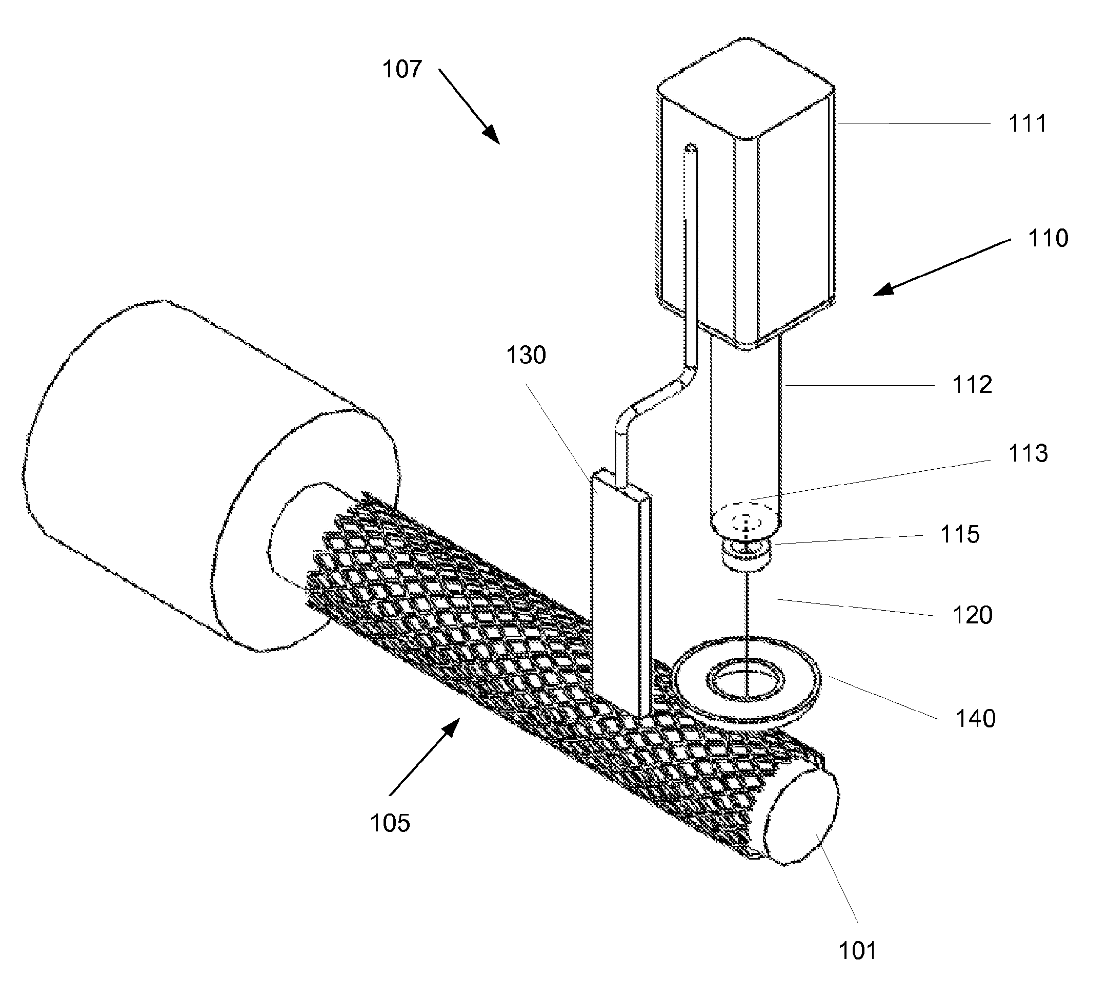
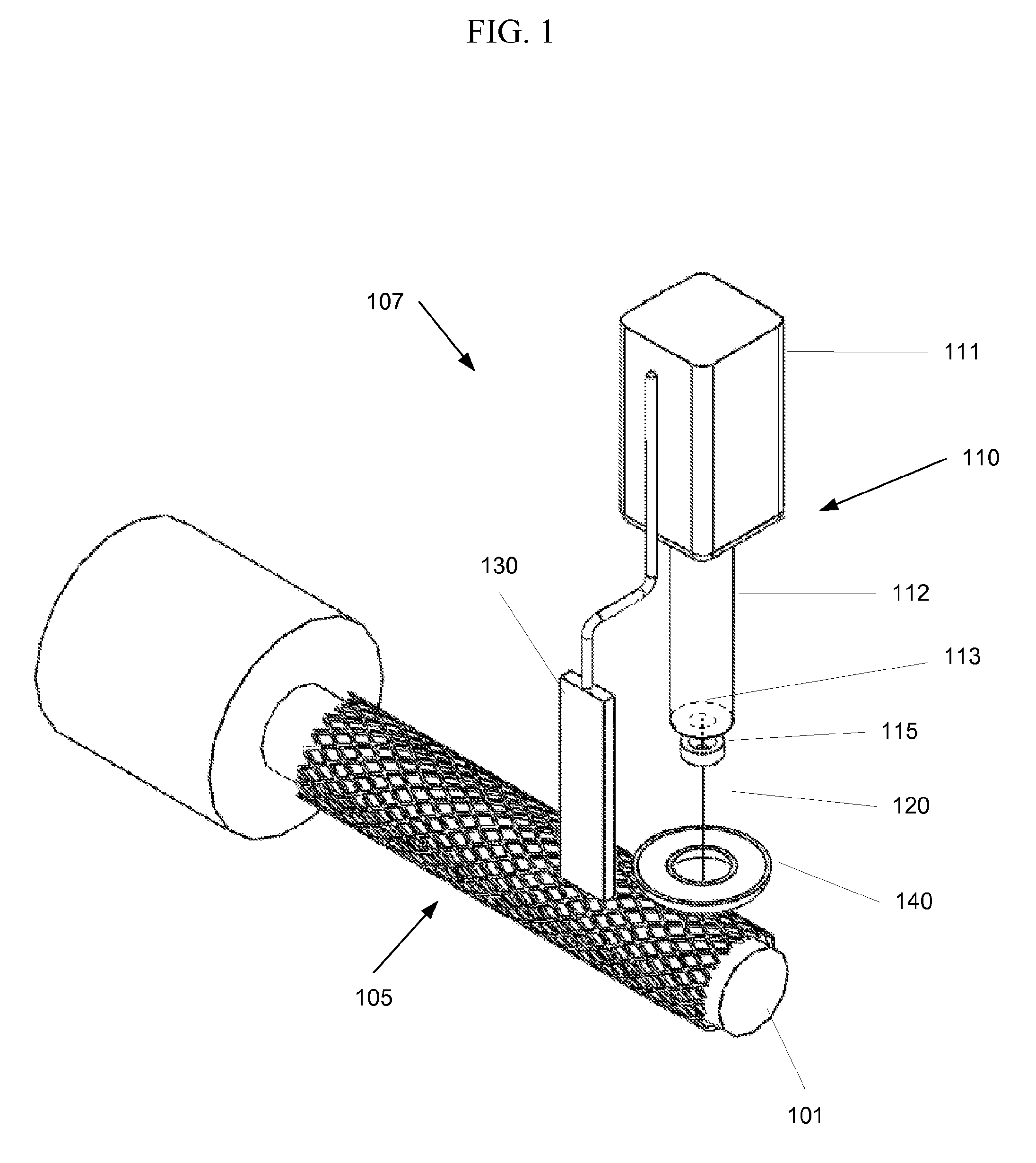
[0018]FIG. 1 shows an embodiment of the invention. A deposition system 107 is used to deposit a coating onto a medical device 105, such as a stent. The medical device 105 is positioned on a support 101. For example, when a stent it to be coated it may be placed on a cylindrical support. The support 101 and the deposition system 107 may be positionable relative to each other. For example, in the system shown in FIG. 1 the support 101 may be rotated by an operator or a control system, and the deposition system 107 may be translated along the length of the medical device 105. In another embodiment, the medical device 105 may be held on a stationary support 101 while the deposition system 107 rotates around the device, translates along its length, or both. In yet another embodiment, the deposition system may be stationary while the support 101 may rotate around the longitudinal axis of the support 101 and / or translate in a direction along its axis. Other configurations may be used. For ...


PUM


Abstract

Systems and methods for coating medical devices are provided that allow for relatively precise control over the deposition area and coating uniformity with improved efficiency. A microdrop source is used to provide a flow of coating microdrops. A charging electrode disposed near the outlet of the coating source gives each microdrop an electrostatic charge. As the microdrop travels toward the medical device to be coated, a control electrode alters the trajectory of the microdrop. The invention can include a scanner to scan or image the medical device as the coating is applied and a control system to adjust parameters of the deposition process based on information provided by the scanner.

Description

CROSS REFERENCE TO RELATED APPLICATION[0001]The present application claims priority to U.S. provisional application Ser. No. 60 / 972,297 filed Sep. 14, 2007, the disclosure of which is incorporated herein by reference in its entirety.FIELD OF THE INVENTION[0002]The present invention relates to coating medical devices, such as stents. More specifically, the present invention is directed to the field of coating a medical device using charged microdrops of a coating material.BACKGROUND[0003]Medical implants are used for innumerable medical purposes, including the reinforcement of recently re-enlarged lumens, the replacement of ruptured vessels, and the treatment of disease such as vascular disease by local pharmacotherapy, i.e., delivering therapeutic drug doses to target tissues while minimizing systematic side effects. Such localized delivery of therapeutic agents has been proposed or achieved using medical implants which both support a lumen within a patient's body and place appropri...

Claims


Application Information

Patent Timeline
Patent Type & Authority Applications(United States)
IPC IPC(8): B05D1/04B05B5/035B05C11/02A61F2/82
CPCA61F2/82A61F2240/001A61F2250/0067B05B1/08B05D1/04B05B5/0533B05B13/0228B05B17/04B05B17/06B05B5/025
Inventor FREDRICKSON, GERALDDOROGY, BILLROBIDA, TODD R.SOJKA, PAUL
Owner BOSTON SCI SCIMED INC
Why Eureka
Try Eureka