
Spectroscopic diagnostic method and system based on scattering of polarized light

a diagnostic method and light scattering technology, applied in the field of spectroscopic diagnostic methods and systems based on scattering of polarized light, can solve the problems of high sampling error, flat and not visually observable forms of atypia and dysplasia, and many early lesions that are often almost impossible to d

Inactive Publication Date: 2009-03-19
NEWTON LAB
View PDF0 Cites 46 Cited by
  • Summary
  • Abstract
  • Description
  • Claims
  • Application Information

AI Technical Summary

Benefits of technology

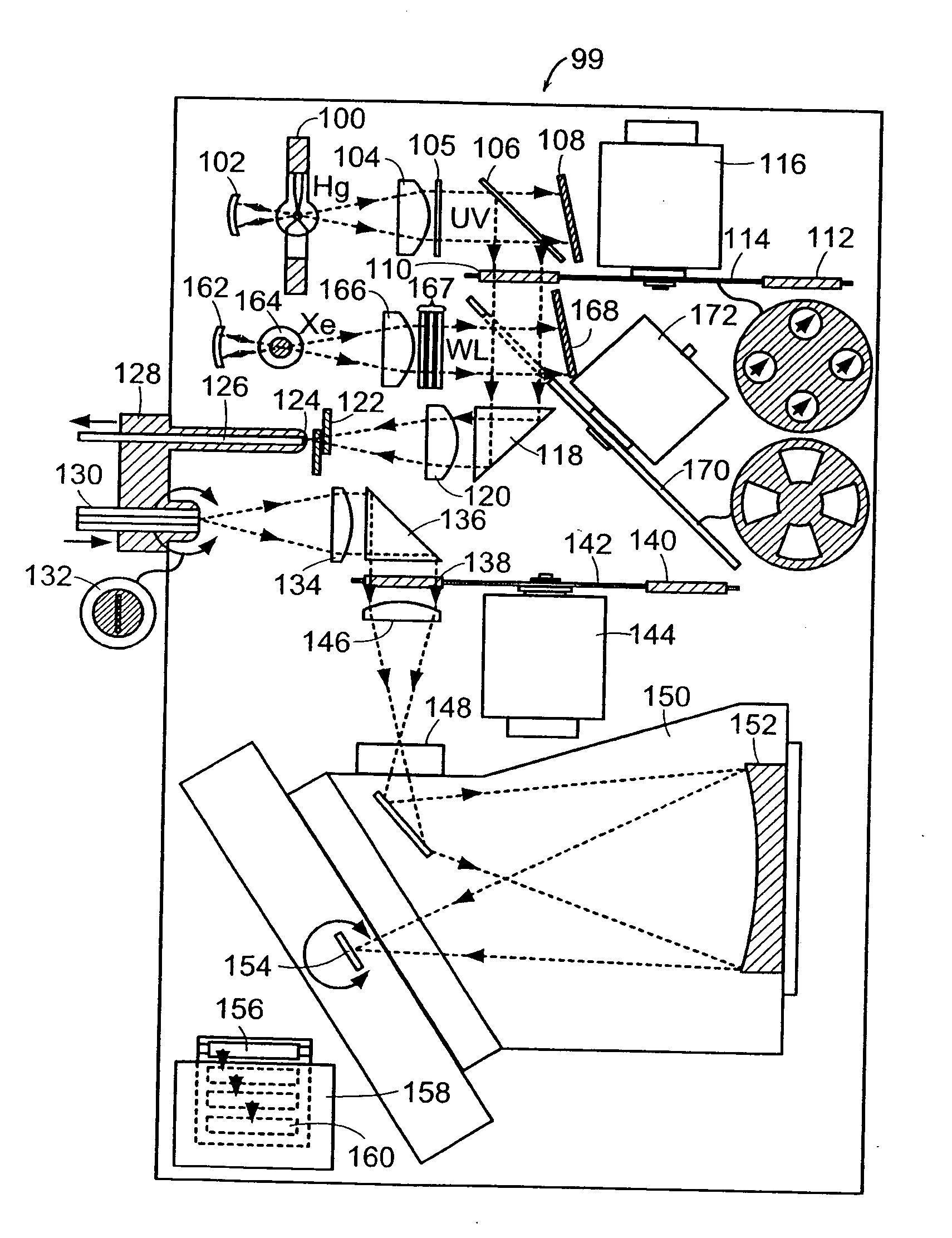
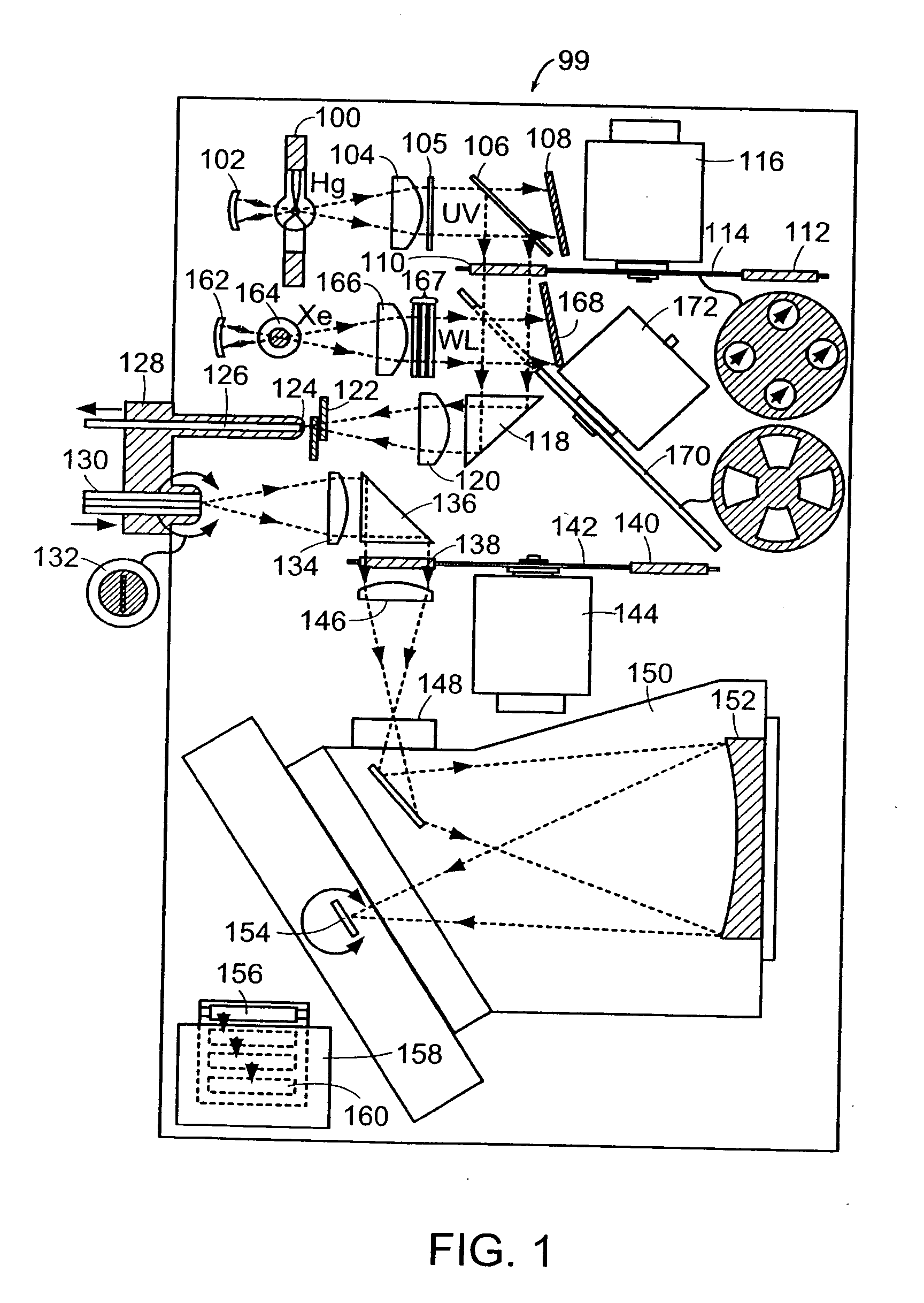
[0020]In accordance with a preferred embodiment of the present invention, a spectroscopic diagnostic system includes an optical probe that provides backscattered spectra so that any underlying fluctuations in the backscattered light spectra appear directly as the result of a differential spectroscopic measurement. In a particular embodiment, the probe is used to detect polarized light. In some embodiments, the probe contains crossed polarizers, while in other embodiments, the probe contains a single polarizer. By using polarized light, the spectrum of the background scattered light can be subtracted out automatically, making real-time analysis possible in place of current off-line analysis methods.

Problems solved by technology

However, many forms of atypia and dysplasia are flat and not visually observable.
However, usually only a small fraction of the epithelial surface at risk for dysplasia can be sampled in this way, potentially resulting in a high sampling error.
However, this approach must be specifically adapted to each different type of tissue studied, and its accuracy is theory dependent.
Although many epithelial cancers are treatable provided they are diagnosed in a pre-invasive state, early lesions are often almost impossible to detect.
In particular, the nuclei become enlarged, crowded and hyperchromatic, that is, they stain abnormally dark with a contrast dye.
These pre-invasive signs have been detectable by histological examination of biopsy specimens, but no reliable optical technique to diagnose dysplasia in-vivo is available.
People who develop Barrett's esophagus may have symptoms of heartburn, indigestion, difficulty swallowing solid foods, or nocturnal regurgitation that awakens them from sleep.
Patients with Barrett's esophagus have an increased risk of developing esophageal adenocarcinoma, the most rapidly increasing cancer in the United States.
Thus, there is tremendous potential for sampling error.
The application of optical techniques to diagnose dysplasia in Barrett's esophagus is limited by the fact that the primary alterations in the tissue occur in the epithelium which is one cell thick (˜20-30 μm) while fluorescence or reflectance spectra are mostly formed in deeper tissue layers.
Unfortunately, epithelium does not contain strong absorbers or fluorophores, and the thickness of the epithelium is relatively small and thus negligible.
These make epithelium diagnosis in Barrett's esophagus a difficult problem.

Method used


Image

  • Spectroscopic diagnostic method and system based on scattering of polarized light
  • Spectroscopic diagnostic method and system based on scattering of polarized light
  • Spectroscopic diagnostic method and system based on scattering of polarized light

Examples


embodiment 237

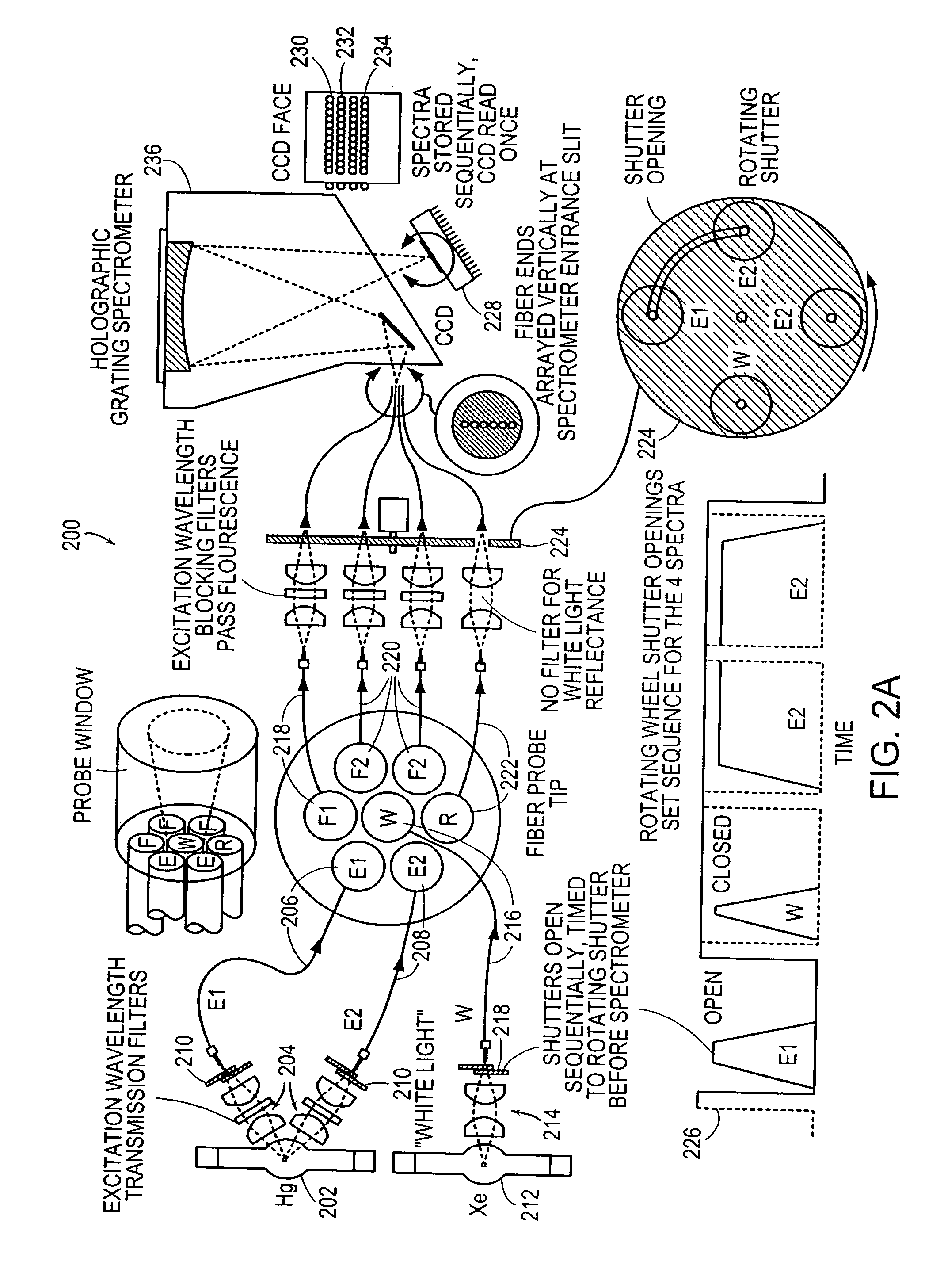
[0069]FIG. 2B illustrates schematically an embodiment 237 in which two excitation wavelengths, E1 and E2, that are sufficiently separated in wavelength that dichroic mirrors 238 can be used to separate the two wavelengths and then recombine them, after additional filtering into one illumination optical fiber 240. The two separate optical paths can also include shutters 242 to provide independent timing of illumination with E1 and E2.

[0070]Another alternative embodiment is shown in FIG. 3A. In this embodiment 300, all of the illumination colors are multiplexed into a single illumination fiber 302 so that all of the remaining fibers 304 can be used for the collection of each resulting fluorescence or reflectance spectrum. This approach has the advantage of multiplying the collected power by a factor of six at the cost of having to shift appropriate filters into the optical paths at the appropriate times, which slows down the overall collection time for the system. Rotating wheels 306,...

embodiment 329

[0072]The schematic diagram shown in FIG. 3B illustrates an embodiment 329 in which a single mercury lamp 330 can be used as a source for corrected broadband illumination (“white light” as described above), as well as several fluorescence excitation wavelengths, E1, E2 and E3. The different wavelengths are selected by movement of the appropriate filters, already discussed above, into the optical path using a filter wheel 332.

[0073]FIG. 4 illustrates an embodiment in which polarized light is emitted from the illumination optical fiber and the light collected by at least two collection optical fibers, preferably by four collection fibers. The details of the relationship of the illumination and collection optical fibers to the polarizer are illustrated schematically in FIGS. 5A-5B for both a single polarizer optical probe (FIG. 5A) and a crossed polarizer optical Probe (FIG. 5B).

[0074]Optical fiber probes for LSS typically transmit white light to the tissue through at least one illumin...


PUM


Abstract

The present invention provides systems and methods for the determination of the physical characteristics of a structured superficial layer of material using light scattering spectroscopy. The light scattering spectroscopy system comprises optical probes that can be used with existing endoscopes without modification to the endoscope itself. The system uses a combination of optical and computational methods to detect physical characteristics such as the size distribution of cell nuclei in epithelial layers of organs. The light scattering spectroscopy system can be used alone, or in conjunction with other techniques, such as fluorescence spectroscopy and reflected light spectroscopy.

Description

CROSS REFERENCE TO RELATED APPLICATIONS[0001]The present application claims the benefit of and priority to U.S. Provisional Application No. 60 / 349,958, filed Jan. 18, 2002 and U.S. application Ser. No. 10 / 347,134, filed Jan. 17, 2003. The entire contents of the above applications are incorporated herein by reference in its entirety.BACKGROUND OF THE INVENTION[0002]It is often necessary to obtain quantitative information that characterizes the features of a surface layer of microscopic objects relatively free from the influence of underlying structures. Light-scattering spectroscopy (LSS) is one technique that can provide the desired information. One such application is monitoring the precancerous condition of the cells in the epithelial layer that cover surfaces or body organs. The ability to measure quantitative changes in intracellular structures in situ provides an opportunity for early diagnosis of cancer or precancerous lesions. More than 90% of all cancers are epithelial in or...

Claims


Application Information

Patent Timeline
IPC IPC(8): G01N21/84G01N21/49G02F1/01A61B1/00A61B1/273A61B5/00G01N21/25G01N21/47G01N21/64
CPCA61B1/00165A61B1/043A61B1/0646A61B1/0669A61B1/2736A61B5/0075G01N2021/6421A61B5/7257G01N21/255G01N21/474G01N21/645G01N2021/6419A61B5/0084
Inventor FULGHUM, JR., STEPHEN F.
Owner NEWTON LAB
Learn More