Distributed RF front-end for UWB receivers

a technology of distributed radio frequency and receiver, which is applied in the field of ultra wideband (uwb) receivers, can solve the problems of reducing the power consumption of distributed architecture circuits, affecting the performance of uwb receivers, and occupying large chip areas, so as to reduce power consumption and chip area of rf front-end.

Active Publication Date: 2009-03-19
RGT UNIV OF CALIFORNIA
View PDF2 Cites 40 Cited by
  • Summary
  • Abstract
  • Description
  • Claims
  • Application Information

AI Technical Summary

Benefits of technology

[0004]Described herein are ultra wide-band distributed RF (UWB-DRF) front-end receivers comprising composite cells distributed along transmission lines, where each composite cell comprises a low-noise amplifier (LNA) merged with a mixer. By merging the LNA and the mixer in each compo...

Problems solved by technology

The main challenge to design wideband, e.g., ultra-wideband (UWB), transceivers is to satisfy gain, NF, reverse isolation, and linearity requirements over a wide bandwidth (e.g., 7.5 GHz in a UWB wireless system).
The input matching and ga...

Method used


Image

  • Distributed RF front-end for UWB receivers
  • Distributed RF front-end for UWB receivers
  • Distributed RF front-end for UWB receivers

Examples


Embodiment Construction

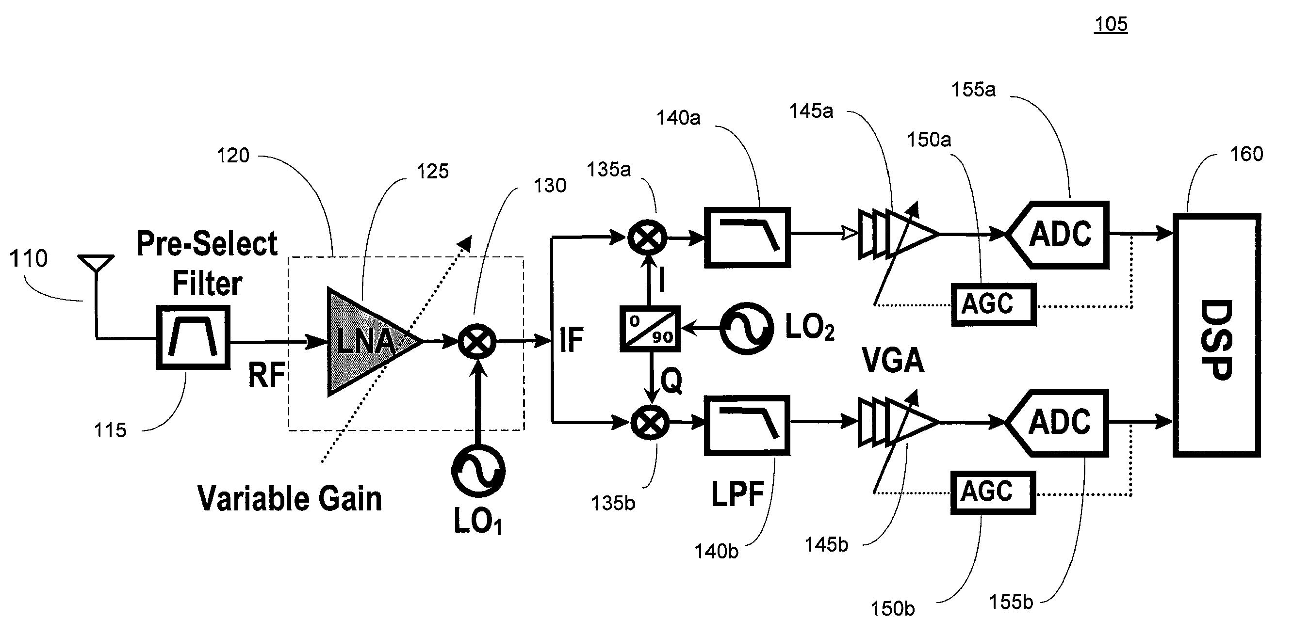
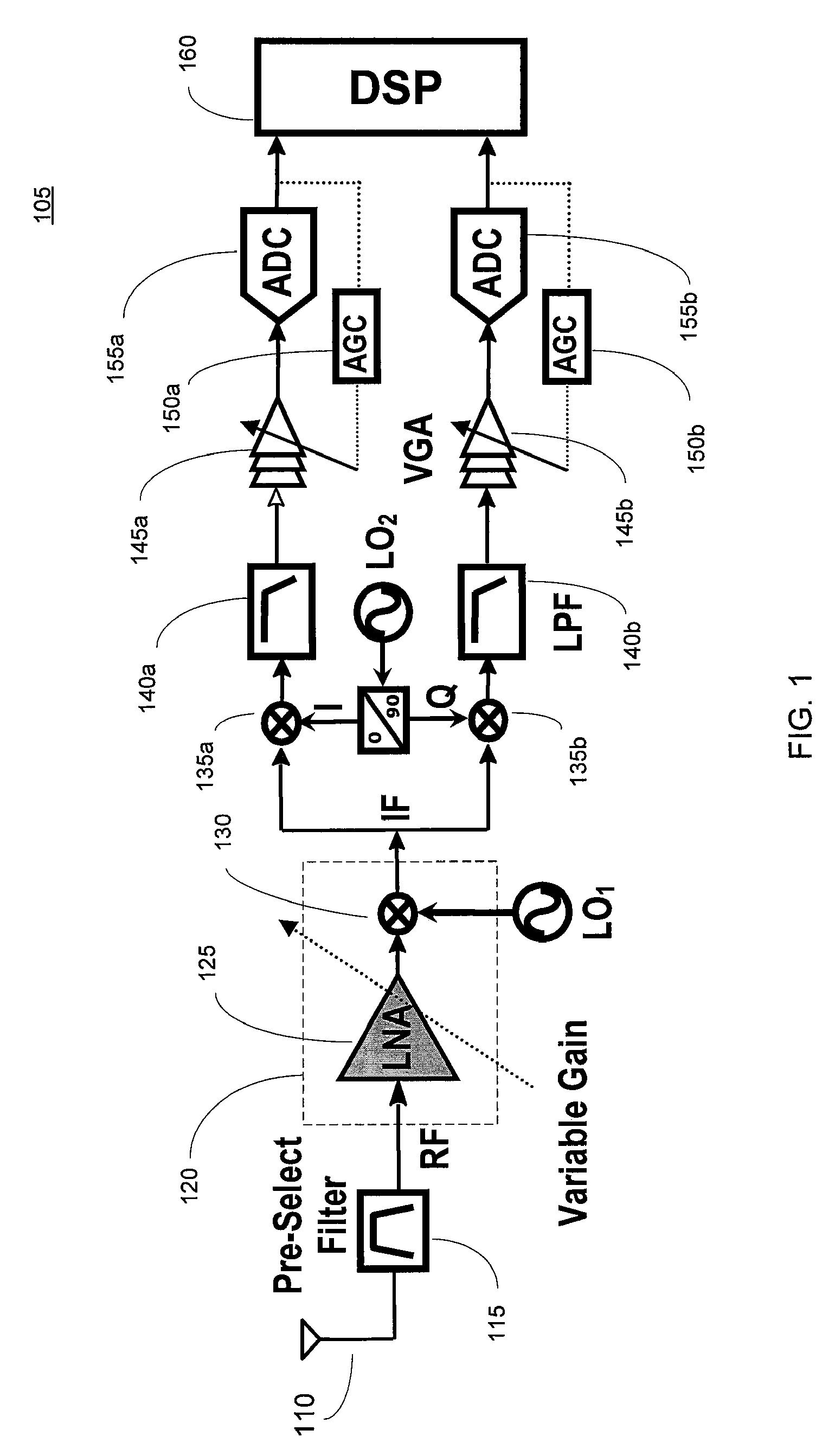
[0023]FIG. 1 shows a block diagram of an exemplary UWB zero / low IF dual-conversion receiver 105. The receiver 105 includes an antenna 110 that receives an RF signal, and a pre-select filter 115 that rejects the out-of-band interferences in the received RF signal. The receiver 105 further includes an RF front-end section 120 comprising a low-noise amplifier (LNA) 125 and a mixer 130. The LNA 125 amplifies the RF signal, and the mixer 130 mixes the amplified RF signal with a local oscillator LO1 signal to down convert the signal to an intermediate frequency (IF) signal. In an exemplary embodiment, the IF signal has a frequency of less than 2 GHz. The in-band image frequency in the IF signal will be filtered out using a Weaver-type image-reject architecture in the second down conversion stage in companion with the digital section. The out-of-band image frequencies are also rejected by the pre-select filter 115.

[0024]The second down conversion stage has in-phase (I) and quadrature (Q) b...


PUM


Abstract

Described herein are ultra wide-band distributed RF (UWB-DRF) front-end receivers comprising composite cells distributed along transmission lines, where each composite cell comprises a low-noise amplifier (LNA) merged with a mixer. By merging the LNA and the mixer in each composite cell, the power consumption and chip area of the RF front-end is reduced. Further, the distributed architecture of the RF front-end allows it to operate over a wide bandwidth by absorbing the parasitic capacitances of the composite cells into the transmission lines of the RF-front end. Embodiments of the RF front-end provide wideband flat gain, low noise figure (NF), wideband linearity, and wideband matching at the inputs of the RF front-end. In an embodiment, a programmable resistance at the termination of the RF transmission line allows the RF front-end to trade off a few decibels of mismatch at the RF input for higher gain and lower NF.

Description

FIELD OF THE INVENTION[0001]The present invention relates generally to ultra wide-band (UWB) receivers, and more particularly to distributed radio frequency (RF) front ends for UWB receivers.BACKGROUND OF THE INVENTION[0002]UWB wireless broadcasts are capable of carrying huge amounts of data up to 250 feet with extremely little transmit power and high immunity to interference and multipath fading. Indeed, the spread spectrum characteristics of UWB wireless systems, and the ability of the UWB wireless receivers to highly resolve the signal in multi-path fading channels make them a desirable wireless system of choice in a wide variety of high-rate, short- to medium-range communications. The ability of UWB systems to locate objects to within one inch attracts the military, law-enforcement, and rescue agencies. Other applications include broadband sensing using active sensor networks and collision-avoidance. The circuit techniques that are used to realize different circuit components in...

Claims


Application Information

Patent Timeline
IPC IPC(8): H04B1/16
CPCH04B1/0092H04B1/71637H04B1/18
Inventor SAFARIAN, AMINGHASEMZHOU, LEIHEYDARI, PAYAM
Owner RGT UNIV OF CALIFORNIA
Why Eureka
Try Eureka