
System, method, and apparatus for reactive foil brazing of cutter components for fixed cutter bit

a technology of reactive foil brazing and fixed cutter bits, which is applied in the direction of welding apparatus, manufacturing tools, non-electric welding apparatus, etc., can solve the problems of changing the properties of metals and other materials used, and achieve the effect of low stress and resistance to corrosion

Active Publication Date: 2009-03-26
BAKER HUGHES INC
View PDF26 Cites 38 Cited by
  • Summary
  • Abstract
  • Description
  • Claims
  • Application Information

AI Technical Summary

Benefits of technology

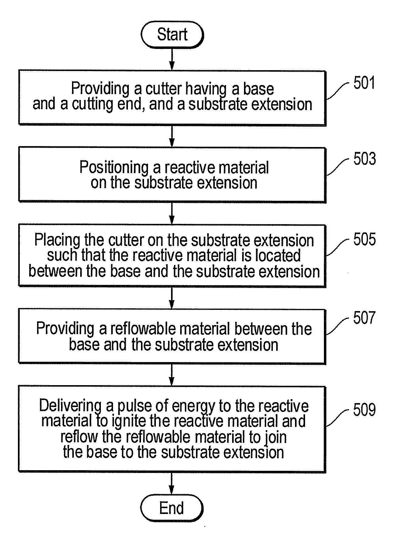
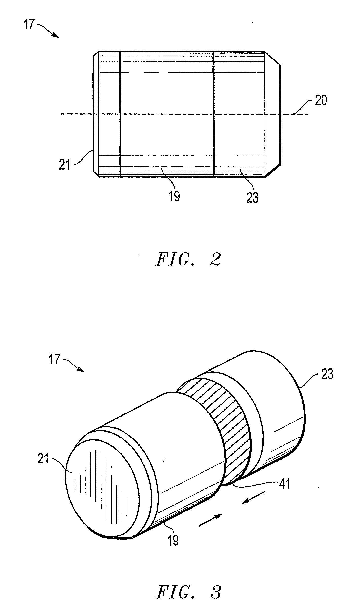
[0010]An effective bond may be formed between the substrate or extension of a rock bit cutter and its cutting element (e.g., tungsten carbide tip) using these techniques. The invention eliminates the need for a standard furnace, torch, or laser weld. Bonds between similar or dissimilar materials (e.g., ceramics to metals) may be formed in almost any environment (e.g., in ambient conditions), and are resistant to corrosion and degradation. The bonds exert low stress on the constituent parts, expose them to minimal thermal demands, and can be produced in a flux free environment. In addition, the invention may be used to join cutting elements to the bit body.

Problems solved by technology

However, the high temperature ranges used to fabricate the bits can change the properties of the metals and other materials used.

Method used


Image

  • System, method, and apparatus for reactive foil brazing of cutter components for fixed cutter bit
  • System, method, and apparatus for reactive foil brazing of cutter components for fixed cutter bit
  • System, method, and apparatus for reactive foil brazing of cutter components for fixed cutter bit

Examples


Embodiment Construction

[0018]Embodiments of a system, method and apparatus for reactively brazing together the components of rock bit cutters are disclosed. The invention utilizes technology disclosed in U.S. Patent Application Nos. 2004 / 0149373, published on Aug. 5, 2004; 2004 / 0247931, published on Dec. 9, 2004; 2005 / 0003228, published on Jan. 6, 2005; and 2006 / 0219759, published on Oct. 5, 2006, all of which are incorporated herein by reference.

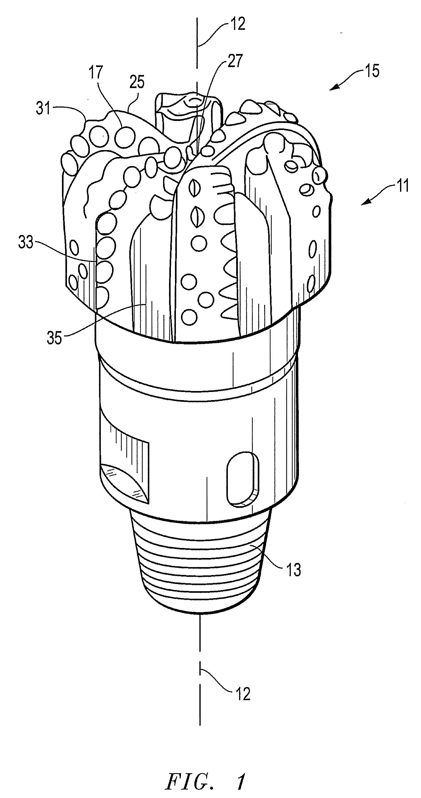
[0019]Referring to FIG. 1, one embodiment of a fixed cutter rotary drill bit 11 is shown. Bit 11 has a rotational axis 12 and a threaded end 13 for connection into a drill string. A cutting end 15 at a generally opposite end of the bit 11 is provided with a plurality of hard cutting elements 17 (e.g., polycrystalline diamond cutters, etc.) arranged about cutting end 15 to effect efficient removal or cutting of formation material as bit 11 is rotated in a borehole.

[0020]The cutting elements 17 typically are secured in a pocket provided on cutting end 15 such that ...


PUM

PropertyMeasurementUnit
pressureaaaaaaaaaa
energyaaaaaaaaaa
shapeaaaaaaaaaa

Abstract

A reactive foil is used to assemble the components of rock bit cutters and to affix cutting elements to rock bit bodies. A small pulse of localized energy ignites the foil in a fraction of second to deliver the necessary amount of heat energy to flow solder or braze and form a strong, true metallic joint. The reaction in the foil may be activated using optical, electrical, or thermal sources.

Description

[0001]This non-provisional patent application claims priority to and the benefit of U.S. Provisional Patent App. No. 60 / 994,983, filed Sep. 24, 2007.BACKGROUND OF THE INVENTION[0002]1. Technical Field[0003]The present invention relates in general to fabricating earth boring bits and, in particular, to an improved system, method, and apparatus for brazing together the components of cutters for fixed cutter bits.[0004]2. Description of the Related Art[0005]Rotary drill bits are commonly used for drilling bore holes or wells in earth formations. One type of rotary drill bit is the fixed cutter bit or drag bit, which typically includes a plurality of cutting elements secured to a face region of a bit body. Generally, the cutting elements of a fixed cutter type drill bit have either a disk shape or a substantially cylindrical shape. A hard, super-abrasive material, such as mutually bonded particles of polycrystalline diamond, may be provided on a substantially circular end surface of eac...

Claims


Application Information

Patent Timeline
Patent Type & Authority Applications(United States)
IPC IPC(8): B21K5/04B23K31/02E21B10/00E21B10/36
CPCB23K1/0006B23K1/0008E21B10/567B23K20/08B23K2201/002B23K20/06B23K2101/002
Inventor LYONS, NICHOLAS J.AMES, NATHAN DAVID
Owner BAKER HUGHES INC
Learn More