Differential circuit providing a function to cancel input offset voltage
a differential circuit and offset voltage technology, applied in differential amplifiers, amplifier details, amplifiers with semiconductor devices/discharge tubes, etc., can solve the problems of reducing the signal quality in the lower frequencies, affecting the gain of the inverting amplifier and the capacitance obtained, and raising the cost of the i
- Summary
- Abstract
- Description
- Claims
- Application Information
AI Technical Summary
Benefits of technology
Problems solved by technology
Method used
Image
Examples
first embodiment
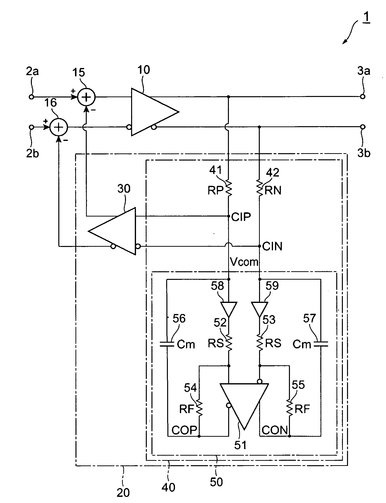
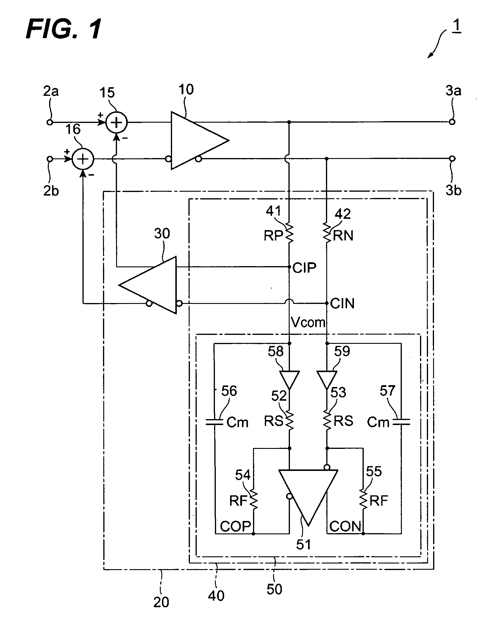
[0022]FIG. 1 illustrates a circuit diagram of a differential circuit and an offset canceller according to the first embodiment of the invention. The 1 provides a pair of input terminals, 2a and 2b, a pair of output terminals, 3a and 3b, a primary amplifier 10, an offset canceller 20 and two subtractors, 15 and 16.
[0023]The primary amplifier 10, put between two input terminals, 2a and 2b, and two output terminals, 3a and 3b, is connected in the non-inverting input thereof with the input terminal 2a through the 15, while, in the inverting input thereof is coupled with the input terminal 2b through the other 16. The non-inverting output of the primary amplifier 10 is directly coupled with the output terminal 3a, while, the inverting output thereof is coupled with the other output terminal 3b. Here, the inverting and the non-inverting merely mean that the signals output therefrom or input thereto have phases opposite to each other.
[0024]The primary amplifier 10 typically comprises a plu...
second embodiment
[0051]FIG. 4 is a circuit diagram of a differential circuit according to the second embodiment of the present invention. The differential circuit 1A has a different feature from those of the first embodiment shown in FIG. 1 that the differential circuit 1A provides, instead of the offset canceller 20, a modified offset canceller 20A. Other arrangements except for the offset canceller 20A are same with those in the first circuit 1. The offset canceller 20A may be distinguished from the aforementioned offset canceller 20 by the filter 40A. The filter 40A provides a trans-conductance amplifier 43 but removes the first and second resistors, 41 and 42.
[0052]The trans-conductance amplifier 43 converts a voltage signal into a current signal. Accordingly, the trans-conductance amplifier 43 may be regarded as a conductive element whose conductance is the inverse of the resistance of a resistor. Because the trans-conductance amplifier 43 has the converting gain, gm [A / V], the filter 40A provi...
third embodiment
[0057]FIG. 7 shows another modified differential circuit according to the third embodiment of the invention. The third differential circuit 1B has a feature to provide another offset canceller 20B instead of the aforementioned offset canceller 20. Other configurations of the third differential circuit 1B are same with those of the first 1.
[0058]The offset canceller 20B provides, in place of the capacitance multiplier 50, a modified capacitance multiplier SOB that includes an Op-Amp 51B. This Op-Amp 51B provides a function to adjust the output level responding to the control signal VCM. The output level of the Op-Amp 51B is desirable to be set in a middle level within an output swing range of the Op-Amp 51B. Other functions of the Op-Amp 51B are same with those of the former Op-Amp 51.
[0059]When the closed loop gain of the Op-Amp 51 combined with the resistors, 52 to 55, is large, the capacitance multiplier 50 occasionally causes the saturation in the output level thereof depending o...
PUM
 Abstract
Description
Claims
Application Information
 - R&D
- Intellectual Property
- Life Sciences
- Materials
- Tech Scout
- Unparalleled Data Quality
- Higher Quality Content
- 60% Fewer Hallucinations
Browse by: Latest US Patents, China's latest patents, Technical Efficacy Thesaurus, Application Domain, Technology Topic, Popular Technical Reports.
© 2025 PatSnap. All rights reserved.Legal|Privacy policy|Modern Slavery Act Transparency Statement|Sitemap|About US| Contact US: help@patsnap.com


